Thursday, July 28, 2016

Power Source From Computer Into a Bench Lab Supply


Power Source From Computer Into a Bench Lab Supply


Here's a quick and easy way to turn an old ATX computer power supply into a bench lab power supply.


Below is a typical power supply from a computer. Some power supplies require a load on them to operate. Some have enough of a load to operate with just the built-in fan running once you turn it on. For a supply that needs a load you'd have to add a resistor. My supply was purchased for $3 at a resale shop and doesn't need a resistor.


So, how can we get this power supply up and running when it's out of a computer? Easy! Just place a jumper wire from the 4th wire to a black wire. Usually the 4th wire is green. It will be the only green wire in the big plug. There will be many black wires. I chose to jump the green wire to the black wire that was to the right of it in position 3 from the right (with the little lock on the connector facing you).

With this setup my supply was able to turn on and its fan started running. Success! I did not need any resistors apparently. 


Theoretically I could have stopped here and just used the plug as a power output. But that wouldn't be much fun. So I kept going.

I unplugged the unit from the wall again and cut all the many connectors off. Cut as close to the connectors as possible to leave the wires longer.


I opened up the power supply at this point to see inside. BEWARE: the capacitors inside this (and any) device will stay charged for months until one of two things happens: either they are bled off by a resistor; or they shock and kill/harm you! 

A capacitor is very much like a battery. It holds energy. When you stick a battery up to a light bulb it will slowly discharge energy to light the bulb for hours. When you stick a capacitor up to a light bulb it will discharge all of its energy instantly: like a camera flashbulb or a stun gun. I wouldn't be doing this if I didn't know what a capacitor is and what they looked like. 

It always amazes me when people take out a flyback transformer from an old CRT television and then ask around as to the "pin-out" of which of the zillion connectors they need to do certain things. Duh! Just take a photo of the item in question before you rip it out of the device! I did this, but it's not really needed because everything on this power supply is color coded.

Here you can see that all the orange wires are +5 volts DC.


Here's a photo showing that the single blue wire is -12 volts and all the yellow wires are +12 volts.


This is the important one: the 4th wire which is usually green! Okay, as you can see the green wire is labeled "PS/ON" for "Power Supply ON". This is the other end of the green wire that we connector to a black wire for the unit to power on. Now you know why this had to be done. I could put an on/off switch between the green and black wire, but my supply already has an an on/off switch.


Here is a photo showing the black wires. They're labeled "GND" for ground / common.


So, when I cut the all the connectors off I took only one of the black wires and kept it tied to the green wire. All the other black wires will be used in a moment.


Loosely tie any black wire to the green wire.


All the colors get separated out and will joined together.


Pencil out a line or two for hole drilling (with the cover off the actual supply). Make sure that you don't end up putting the output holes right over the large heat sinks inside the unit or else the wires will be pinched on their way out of the unit. 


Okay. Here we are: all the wires (except 4) are exiting the unit. I could have stopped here and soldered all the different colors to themselves and used the supply.


bought some INSULATED binding posts. Actually they're banana plug females. Where they touch the case they are PLASTIC and the little metal rings that tighten them to the back of the metal casing doesn't make contact with the center connection of each jack. If you used a plug or post that has a metal thread that touches the metal case YOU WILL DESTROY YOUR SUPPLY AND BE SHOCKED/ELECTROCUTED. 


Shocked means that electricity traveled through part of your body. Electrocuted means to be executed via electricity. It's a subtle difference I suppose. This unit is capable of up to 35 Amps. Enough to destroy most multimeters if you tried to measure the amps without a high voltage divider probe. I thought, "hmmm...that's weird, let me try my cheap meter on its 10 Amp setting." The result was that the meter wires heated up instantly and I pulled it away. I was lucky, but forget about measuring the amps. I had no issues with the voltage measurements and my multimeter wires plugged into their normal sockes: the black common/ground and the normal red plug (not the 10 Amp red plug).


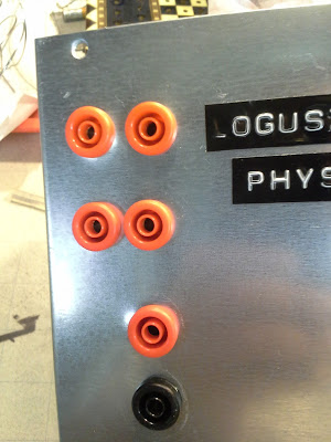
Here are the banana plugs installed. Much nicer than bare wires sticking out of the case.


Here are some power leads plugged into my power supply.


Here are the results with no load other than the multimeter and the internal fan going. I printed a copy and pasted it to the top of the unit.


A recap of what wires did what including the 4 wires that didn't get connected to banana outputs.

Yellow +12V

Blue -12V

Red +5V

White -5V

Orange 3.3V

Black Ground/Common

Purple +5V always on "SB" Stand By mode.

Green PS/ON

Grey +5 PG feedback "Power Good"


Okay, so one of the black wires was soldered to the green wire. All the rest of the black wires were soldered to the COM/GRD output.

The purple wire always has 5 volts running to it, even when the power switch is turned off on the supply. If the supply is plugged into the wall it has power. You can hook a red LED up to the wire and then you'll know when the power supply is plugged in but not turned on. I didn't want to waste a black wire for that setup.

The grey wire is the "Power Good" feedback wire. If the power supply is running properly this wire will give out 5 volts. You can hook this up to a green LED and then you'll know when the power supply's on/off switch is set to on and everything is functioning properly. Again, you'd have to pair it to a black wire, which I didn't feel like doing.

So, why didn't I just use one each of all the colors instead of bundling them all together with solder? The thicker the wire (or the more little wires soldered together) the more amps it can handle. They were there and it was fun so why not build it to withstand anything it can theoretically put out.


So there you have it. My project in a nutshell:

1. Jumper the green to black to see if it'll start up without adding resistors.
2. Cut the connectors off.
3. Bundle all the same colored wires together and solder them (all the reds together, etc.).
4. Solder the green to a black.
5. Cut and tuck away the grey and purple wires.


That's it really. The other steps were drilling holes and making it look pretty with the banana output connectors. Then testing voltages and labeling the outputs.

After that I just slapped a "Logusz Particle Physics Lab" sticker on it...because it was laying around.

The power supply hooked up to just a multimeter is very stable. The voltage changes just .01 volts over time. The -4.72 voltage changes to -4.71 volts and back repeatedly. Not bad, but then again this is a regulated power supply! 

A regulated power supply is designed to provide stable voltages. They can typically keep the voltage (or current) stable with a narrow range. They're perfect for delicate electronics such as computers.

This is also a switching power supply which means it flicks on and off to manage the power and stability issues. This makes it lightweight, which is good for carrying around and it consumes less input energy too.

I paid $3 for the power supply at Disabled American Vets (DAV), which is a resale shop just like the Salvation Army. The banana connectors were super expensive: a whole bag for $12. These were the cheapest insulated for use on metal boxes ones I could find at the time.

Uninsulated ones are around $4 for a few, but they're only for plastic cases: you'd die if you used them on a metal box like this. I had a bunch of Amazon points so I basically got theses free anyhow.

It was fun and thus worth it to me.


Saturday, July 16, 2016

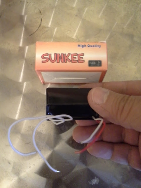
SUNKEE DC 3V to 7KV 7000V Boost Step-up Power Module High-voltage Generator


SUNKEE DC 3V to 7KV 7000V Boost Step-up Power Module High-voltage Generator


3.4V DC in 7000V DC out!

I have a huge, heavy neon sign transformer  (NST) that puts out 5000 volts (5kV) at 18 milliamps (0.018A) and this little box puts out a much scarier spark, although the this doesn't seem to travel through stiff wires so I couldn't make a mini Jacob's Ladder out of it (yet). I'm thinking that means it has very low amps...I haven't measured it yet (use a high voltage divider probe or else you'll wreck your multimeter).


One side has 2 white (or red) wires: those are your outputs. Mine has 2 white outputs.

The input side will have two DIFFERENT color wires (1 red and 1 white). You have to hook positive input to the red. Hook negative input to the white.

In my photo the tips of the output wires are exactly 1/4" apart. The input voltage was 3.3 volts DC. The spark was loud, blue and awesome! Very crackly like a stun gun in the movies. I built a demo fusor (and made the Plasma Club) yet this seems scarier!

You must input DC voltage. You probably shouldn't go over too high or so, although I did momentarily and got a huge spark. The specs say 3 volts. I needed 3.4 to get a steady spark. I'll update if I blow it up and I'll include the final voltage.

If you have the wires farther than 1/4" then either it won't spark or you'll crank up the voltage really high to get a spark: either way you might destroy this device.

If you apply voltage and don't provide an escape for it (a spark or powering something) you can destroy this unit. That's another danger of trying to make a bigger spark gap: you'll be powering this unit but if there's no spark you can destroy this unit apparently. I think that's what the advert means by "don't let the pressure build up" meaning to keep it under load.

For about the price of a single firework you can play with this. I haven't destroyed mine yet. It fills the room with ozone quickly (toy train / slot car smell).

Get a sturdy holder apparatus for the output wires so you don't die.


It came in a cute box, but no instructions other than to keep it away from static. I have a feeling that if you rubbed this on a static wool sweater you might kill yourself with it.

Not bad for $7 on Amazon!


So, besides making the world's tiniest Jacob's Ladder what else did I make with it? An alpha particle spark detector!


Yep, just dial down the input voltage until the sparks sputter out. Then I moved a piece of radioisotope AM-241 (Americium) close to the L-shaped wires. ZAP! The alpha particles get ionized between the 7000 volts of awesomeness.

Check out my previous posts on a bunch of other alpha particle spark detectors, ionizing radiation chambers, nuclear cloud chambers and general Geiger counters.

Another neat thing about the electric arcs generated by this setup is that it reads incredibly COLD on my infrared thermometer! I'm not sure why. Here is my current guess before researching:

Theory 1: the sparks create ozone gas. Ozone has low emissivity: it absorbs infrared radiation. Gases (and dusty conditions) also give false low reading for IR thermometers as well. They gaseous ozone doesn't let the infrared radiation travel to the thermometer: the result is an ultra cold reading.

This is similar to how the sky will look utterly black through infrared heat cameras.

Theory 2: it is known that electromagnetic waves in excess of 3 volts per meter at 90-360 MHz will interfere with IR thermometers. I've got 3.4 volts DC turning into 7000 volts of fast pulsing sparks.

Theory 3: maybe the emissivity of the sparks are similar to that of shiny metal: terribly low. Simple IR thermometers are set to .95 emissivity. Spray paint a piece of aluminum super velvet-black and it will approach 1.0 emissivity. Shine that aluminum with steel wool and it will drop to around 0.003 emissivity! Basically invisible to the IR thermometer.


Thursday, July 7, 2016

DEMONSTRATION FUSION REACTOR (FUSOR)


DEMONSTRATION FUSION REACTOR (FUSOR)


I've finally gotten the purple plasma glow in my demo fusor!


I cannot resize or move images around so this post will stay ugly for a while [updates later] but there is a good reason: the pictures hosted here are linked to my (now successful) application for entry into the Plasma Club at fusor.net!


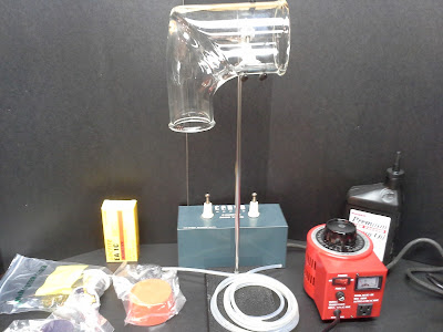
Here are most of the components of my demo fusor.


Shown above are:

Pyrex glass laboratory drain pipe "vee" mitered elbow fitting used as my vacuum chamber.
One opening is 3" inside diameter and the other is 2" inside diameter.
I bought it on eBay for $14.99 plus $11.99 shipping for a total of $26.98

Variac brand variable transformer for varying the ac input to the power supply.
This is the 5 amp 500VA version. SC-5M. My power source is 5000v at 18 milliamps, so 5000 x 0.018mA = 89 watts which is basically 89VA. The 5 amp Variac is obviously capable of handling the 18mA. On the faceplate of the Variac it states a maximum of 500VA which again is way more than my 89VA power supply needs. Amazon $81.24

Cenco 5000v AC output spectrum tube power supply. Cenco model #87208
Came with a 3 prong cord. No ground fault interrupter to cause problems. I tested it by making a Jacob's Ladder with it and it didn't explode. It came with 2 unattached wires that a little research showed were for an on/off foot switch. I just connected these wires to each other and tucked them inside the unit.
Antique Shop $4. 

Silicone (clear) covered high voltage wiring rated at around 6 times my voltage and amps.
This wire is limp like a wet noodle, some people call it "noodle wire". This wire is capable of handling 44,000 Volts AC and 31,000 Volts DC. Way more than my 5000 Volts. It can also handle up to 11 Amps. Again, way more than my 0.018 Amps. Always check Volts & Amps! I bought 10 feet. McMaster-Carr 962T15 $20.80

Silicone Rubber Stopper. 2 13/64" for the 2" hole. Purple. 
NASA has a free off gassing website showing which materials lose more weight after being subjected to a vacuum. Nitrile loses over 1% of its weight in a vacuum: meaning 1% of it flies out into the vacuum chamber and ruins your level of vacuum. Silicone only outgasses 0.31%, so it's way better! In a deep vacuum even the oils from a fingerprint outgas and mess with the vacuum levels. NASA outgas list:
https://outgassing.nasa.gov/cgi/uncgi/search/search.sh
McMaster-Carr 922K79 $5.34

Silicone Rubber Stopper. 3 35/64" for the 3" hole. Red.
McMaster-Carr 9277K71 $16.81

Stainless steel wire 302 steel. 35 feet (1/4lb). Bend and Stay. (0.051" diameter).
Used to make the inner and outer grids. This didn't work as well as some thin scrap copper I found, but didn't melt.
McMaster-Carr 8860K16 $6.51

Alumina Aluminum oxide ceramic rods with two 0.063" inner diameter holes.
It was 2 feet long and impossible to cut with a variety of cutting wheels. I eventually just clamped it in a vise and tapped it with a hammer to break pieces off.
Amazon $11.20

Laboratory stand for assembly, but not actual use. Cast iron base.
Amazon $14.67

Eisco 90mm Lab Clamp.
Super nice clamp that was the only one I found that could hold my huge vacuum chamber.
Amazon $14.20

A 3 CFM 22.5 micron Philadelphia brand vacuum pump.
It sprays out a fine smokey mist, but that mist doesn't seem oily and dissipates. A while later the pump starts leaking oil. This is all considered normal. The pump wasn't too loud either.
It came with slightly more than enough vacuum oil needed.
Harbor Freight with a 20% off coupon and shipping for $143.08

Valve manifold fitting consisting of two ball valves. 
One valve seals the vacuum chamber, the other allows the vacuum pump be routed to open air seconds after it is shut off. Without this valve vacuum pumps would spit oil and condensation into the vacuum vessel. This happened once to me when I forget to let the pump up to air.
Free gift from my father!

Pipe Thread Compound with Teflon
Used by plumbers (and me) instead of Teflon pipe tape. Never use tape on vacuum fittings. This is a liquid paste made by PlumbShop #PS2434.
Local hardware store $1.98

Safety full face mask (probably the most important item of all).
Got it free from my father.

Not shown: a free mini desk fan to cool down the vacuum pump which got incredibly hot, misted and smoked and wept oil, but did the job! I bought some other components but didn't need them. I used a vise, wire cutters, hammer and drill press (to make a hole in the 2" rubber stopper). I also used the lab stand and clamp to hold the glass vessel while I assembled everything-it really helped.

So? What's a fusor? It is an Inertial Electrostatic Confinement (IEC) device.  This is a demonstration fusor; but if I added deuterium gas it would fuse hydrogen atoms together and produce neutrons and x-rays. With the gas it was just creating plasma from residual air molecules in the chamber. As a safer demo model it still produces: UV light; an implosion risk in the glass vacuum chamber; and a whole lot of opportunities to accidentally touch 5000 Volts.

This is a Farnsworth type fusor: developed by Philo T. Farnsworth. You know him right? He was the man (child) who invented television sets at age 14. Yeah, that guy!

I left the chamber under vacuum for 12 hours and when I returned it was still holding the vacuum and was able to create purple plasma!

So what is plasma? It's the fourth state of matter, besides gas, liquid and solid. When a gas is at very high temperature (or energy level) electrons start tearing away and leave behind positive ions. Every Volt an ion crosses imparts 11,604 kelvins. 5000V x 11,604 equals about 58 Million kelvin! While the 2" downward facing section of the glass chamber stayed perfectly room temperature, the 3" business end was hot to the touch. While this 58 Million kelvin is hotter than the surface of the sun, the density of the ions is low: thus I didn't melt the glass.


This is a working schematic of my fusor: 


Here is my fusor with pretty much everything shown for operation. The only thing not pictured is the red Variac transformer which acts as a dimmer switch for the AC electricity input.


Variac transformer showing the important info: it can handle 500VA (which is close enough to 500 Watts). And it can handle 5 Amps. My power supply was only 0.018A x 5000V = 89VA which is close to 89 Watts.


This is my nicest stainless steel inner and outer grids. They got me purple plasma, but didn't operate quite as well as the thin copper.


A "manifold" free from my father. It's two ball valves and some pipes and a huge 3/4" hose barb that I jammed into the purple silicone rubber stopper.


Purple plasma! Electrons being stripped off creating positive ionization.


Yes, it looked this wild and purple in real life!


Full face shield that protects your face and neck, in addition to your precious eyes! These are less than $20 on Amazon with free Prime shipping. Plenty to choose from. No excuse not to use one!


My thinnest grid: I tried thin copper instead of stainless steel. The result was way better, but as you can see the spherical grid sort of melted into a blob.


Big things come from small beginnings.