These are little black balls I found inside of an old hard drive I just took apart. They are charcoal. Activated charcoal pellets to be exact. Like tiny versions of the charcoal briquettes you might use in your barbeque grill, which were invented by Henry Ford.
You burn something with carbon in it (most things in the universe) while providing lots of oxygen. The result is very porous charcoal. The pores are shallow like the dimples on a golf ball. They increase the surface area and help soak up poisons and other contaminants like gases in the air.
In hard drives they're in a little cup with a vent on one side and gauze on the other. This acts as an air filter for the hard drive. I had the same setup for my aquarium when I raised pufferfish! A gauze pouch with charcoal pellets for cleaning the water.
SiliCON vs SiliCONE vs Carbon
The carbon pellets are also super bouncy. Like, oddly bouncy. Way more than the polymer ball we made a few posts back. That surprised my, but a quick glance at the Periodic Table shows that carbon lives right above silicon, which you'll remember from the non-Newtonian fluid and polymer post and the fast that it's what makes Silly Putty so bouncy...well, that's silicone with an "e" at the end polymer made from silicon. Carbon forms much more stable bonds than silicon, but it likes other carbons to bind to. Silicon likes oxygen, and although it's less stable than carbon bonds silicon plenty of molecules-great molecular subunits linked together (very bouncy). Silicone rubber (which is a silicon polymer) has a Young's Modulus of 0.001 and carbon is less elastic at 4.1.
Balls bounce one way, balls bounce the other way. Meow.
Here is one on the xyz stage of my microscope. The white disk is actually the other side of the black cup/filter assembly it was in with a zillion of its pals. A little ways below I have a better photo of this cup.
Here's some various videos made with 3 different cameras, a very nice microscope and some really terrible out-of-sync lighting. This gives a good sense of their miniscule size.
The very same from my previous video: little black balls I found inside of a hard drive I just took apart.
They are charcoal. Activated charcoal pellets to be exact. Like tiny versions of the charcoal briquettes you might use in your barbecue grill, which were invented by Henry Ford.
They're in a little cup with a vent on one side and gauze on the other. This acts as an air filter for the hard drive. I had the same setup for my aquarium when I used to raise Figure-Eight pufferfish!
In this video I put them under a very nice microscope...but with a very cheap ($1.99 used) webcam and terrible side lighting. My microscope has very, very, very good lighting for looking at slides and other things properly prepared for microscopy with the light coming from *underneath* the slide-not from the side.
Also a point of annoyance: I was testing a crappy webcam (an ancient GE model) that I bought used for $1.99. The flicker is from the LED flashlight not syncing with the webcam.
So, a lot of ugliness on this one. Check my other videos for better cameras (a big Canon in HD, but also my cheap Samsung cellphone and Nexus tablet have way, way, way better video than this GE webcam).
This video was: cheap camera, cheap flashlight just as a quick peak. On the blog post I'll put some better looking still photos.
For a $1.99 I finally have a webcam. At some point I might bash the lens off of it and point its CCD array straight into a dark container with a photo-amplifier tube / scintillator in it to create an alpha particle radiation detector. Sort of like the alpha spark detector I made a video of, only digital.
The microscope is actually very nice (stereo eyepiece, xyz stage, abby condensor, LED with electronic dimming switch and various mechanical shutters for dimming and changing the incidence angle of the light, 2000x oil immersion lens: basically all the bells and whistles and the highest reflected normal light magnification physics allows! All coupled (today only) on a webcam that costs less than a can of Red Bull, lol.
I was also holding the webcam with one hand while moving the xyz stage and focusing with the other--I'm being terribly unprofessional today. I actually have a side illuminator for microscopes that I could have used also. It has a nice (non-harsh, non-flickering light) but this was only a test and with the lousy webcam it would't have made much of a difference.
I kept changing video cameras, but kept the lousy lighting.
Speaking of old technology, I also found this cool brochure for coin operated computers for our library. Pineapple Computers!
Neat, but my computer glows in the dark!
I don't care about the black balls, but I need you to make sure none of these old hard drives have any snakes in them! Mee-yow!
If you touch copper wires to a drop of saltwater on aluminum you can hear decaying and regenerating synthesizer-like sounds! I stole this idea from Nyle Steiner, who I gained tons of information about thermocouples from for the last post. Mr. Steiner is the inventor of a variety of Electronic Wind Instruments and has played on a ton of TV and movie soundtracks-good movies too, like Apocalypse Now!
So, what do you do to make the aluminum scream like the metal coins did in dry ice a few posts back? I did this:
Run two copper wires to a speaker or guitar amplifier.
Join the wires together with a resistor of at least 100k value.
Touch one wire to the aluminum.
Touch either the insulation of the second wire to the aluminum with a little saltwater on it OR carefully touch the copper part of the second wire to a droplet of saltwater on the aluminum WITHOUT touching the aluminum.
You can just attach the wires to the end of a guitar cord, the other end of the cord is of course plugged into a guitar amplifier.
Soda cans are made of aluminum.
Both wires are bridged together with a resistor. Use one that's 100k or more. I tried a few different values and heard no difference, but I didn't try many put out and I had them parallel, not in series.
It seems that I got more complex sounds when touching the wire, or just the rubber insulation to corroded or damaged parts of the aluminum.
Here's a taste of the weirdness in video/audio:
...do you still hear the aluminum screaming Clarice?
So, what's going on? Well, if you hook up a multimeter you'll find aluminum plus saltwater produces voltage. The voltage is variable. So this may be like a keyboard synthesizer Voltage Control Oscillator (VCO). Saltwater on aluminum foil can be used to create an ultra simple electrolytic battery that can power an LED. Changing voltages makes noises, whether it's steel guitar strings affecting the magnetic field of the guitar's pickup, a microphone diaphragm moving because of human voice sound waves or this crazy setup.
To juice up the electrolytic aluminum and Saltwater battery you can add lye. What would that do to the sound output of our saltwater synthesizer?
Would solid core copper wire sound different? How about different concentrations of saltwater? Burned aluminum? Aluminum that's being heated or even red hot? How about lemon juice instead of saltwater?
This is a great thing to have on the shelf for future experimentation when nothing else is going on. It's simple and easy to change variables in this little circuit.
By playing around you can obtain incredibly complex noises that evolve and sound like Electronic Music. It's really, really weird.
The Power of Cold (and Hot) II: Thermoelectric Generator
A few posts ago (The Power of Cold and Hot) we looked at a Stirling Engine, which converted temperature differences into pressure and fast movement.
Now we are going to make a thermoelectric generator (and a thermosistor).
A thermoelectric generator converts temperature differences into electric voltage.
Two copper wires heated until they are crusted with cuprous and cupric oxide.
When touching, the wires are pressure sensitive and heat sensitive where they meet (pressure and heat at the junction cause Ohm resistance to drop). This is a thermosistor: resistance varies with temperature.
Heating only one wire causes Voltage to be produced. This is a thermoelectric generator / thermocouple. With only a butane barbeque lighter I can produce a consistent -5.2 mV (millivolt) when I apply ice to the other wire.
The weird thing is that the eV (electron Volt) work function is 5.2-5.6eV for cupric oxide and 4.8-4.9eV for cuprous oxide. Coincidence? Yeah, probaby...
Store bought thermocouples for home appliances produce 25-30 mV with 30mV being the norm.
I've looked at the work of Nyle Steiner who is a real whiz in many areas of electronics. Here's how I built my version:
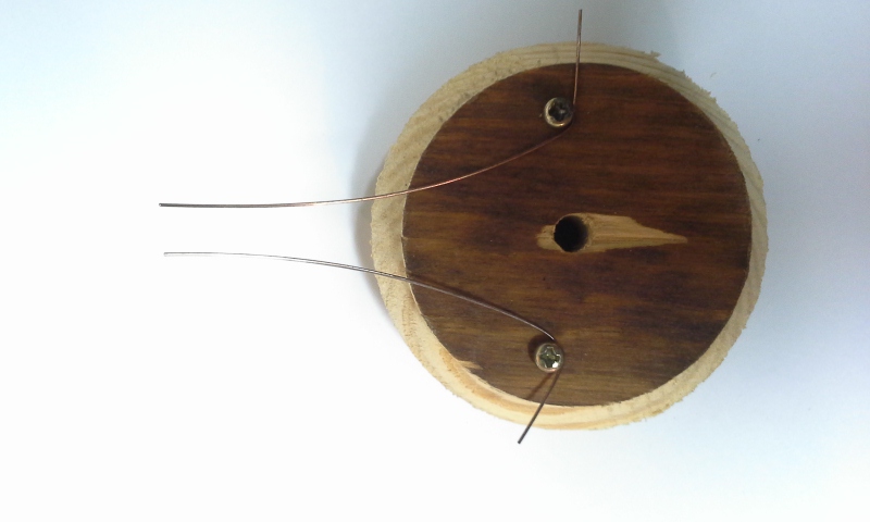
Copper wire of equal lengths.
Wood disk and mounting screws.
Heating with a propane torch. It's hard to see here but the blue flame of the torch turns green after passing the copper wires.
Below you can see the scale left after heating. Red is Cu2O which is cuprous oxide (Copper I). Black is CuO which is the cupric oxide (Copper II). These oxides are used in semiconductors.
With two copper wires the hot wire output is negative voltage and the cooler wire is positive. Nyle Steiner hooked 16 of these wires together and heated them. The result was enough voltage to light up and LED!
Simple thermocouples like this are used to measure temperature in appliances: different voltages equal different temperatures. This is because temperature gradients produce an electromotive force (emf).
Here's a picture of my new Pyrometer (like a thermometer but for surface temperature). It can read up to 800° F and takes no batteries since the operating voltage comes from the physics we're discussing in this post.
Thermometers measure temperature. Pyrometers measure surface temperature. My pyrometer has a blunt tip for placing near the exterior surfaces of things that are very, very hot. Most thermometers are pointy for jabbing into things for interior readings: into a roasting Thanksgiving turkey, into container of boiling liquid, into your mouth, etc.
Newer pyrometers use infrared, lasery thingies that can tell you if the outside of your turkey is too hot from the other side of the kitchen! Here's a photo of mine:
Of course that's pretty useless since you want to measure the inside of the turkey. The problem is that thermometers need to touch what they're measuring, which is fine for normal things but not great touching something that is 800° F or way hotter like smelting metal! Because they don't have to make physical contact you can use a pyrometer to measure the temperature of a moving object, like a stream turbine.
Nowadays pyrometers also have probes for jabbing into things, so the lines are blurring even more. Thermometers generally are more delicate, require contact and can't handle high temperatures.
These sunny-side-up-eggs are starting to burn!
My pyrometer above is made by West Instruments, another company that makes this sort of thing is Borg. Yes, the same Borg from Star Track, or was is Star War? Anyway, BorgWarnet makes stuff for kitchen ovens, which is where I got the circuit board below, although the sensing portions and timer were probably made by Diehl. I think they're the same Borg that makes turbochargers for Detroit Diesel up the street.
...anyway, back to metal thermocouples:
With wires of two different materials, copper and steel for example, you create a closed loop thermocouple that is very similar to our Sterling Engine...but with electromagnetic waves!
All you have to do is solder the two ends of the copper and steel wire together. Then apply heat to one of the solder joints. The greater the temperature differential-the more mV it will produce. Since it's a closed loop of (two) wire there are no "ends" for positive or negative multimeter attachment so it's easiest to use a compass needle to observe electric (and thus magnetic) production.
This is how Seebeck Effect devices such as this, Peltier Cooling Modules and Stirling engines can be used to produce electricity-some improvised units can make enough to charge a cellphone!
Like most things electromagnetic, you can use the output (voltage) and get the input (heat) just by reversing things. Running electricity through a shorted wire produces heat. This is called ohmic heating / Joule heating. It's why short circuits get hot, but it's also how a toaster works, and hot wire saws for sculpting sheets of foam for car seats.
EMF: electromotive feline. The moving clouds and warm sun make me move back and forth. Meow!
...actually, capacitance is measured in farads. Ohms are a unit of resistance.
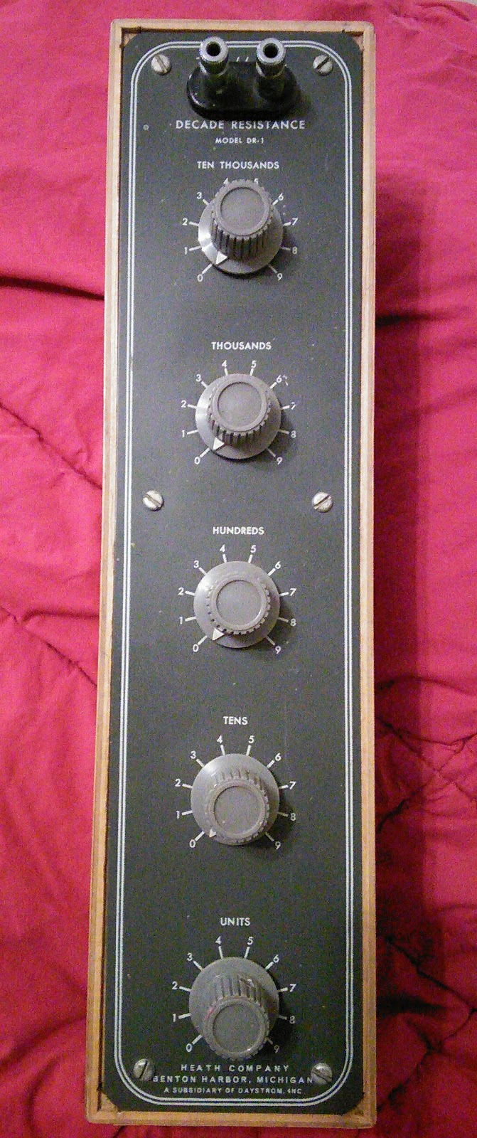
Here is my Heathkit decade resistance box. Each knob varies the amount of resistance by units of one, ten, hundred, thousands or ten thousand of Ohms, thus the "decade" part of the name. Heath was a Michigan-based company that provided kits to make clocks, tube amplifiers, test and radio equipment, etc. This decade box is huge, at over a foot long and had a nice wood enclosure.
I bought this box at the Disabled American Vets (DAV) resale shop by my house for two dollars! It was already assembled. I knew it dealt with ohms, but I thought it might be for stereo speaker setup or something. Speakers commonly refer to ohms in their specifications. It just looked cool.
I like the idea of having a zillion resistors of different values in a convenient box. Did they have things like this for other circuit board components? Yep, I found a nice kit to solder of a bunch of capacitors. Instead of resistance in ohms, this deals with capacitance in farads.
Here are some brief photos of the assembly, which consisted of plunking in a small pile of capacitors:
I left the leads of each capacitor really long...they don't look like much, but capacitors store energy, so if you touch this board you'll get a nice sizzling feeling. A bunch of posts ago (So You Wanna See Atomic Particles With Your Own Eyes Huh, Part 3) we dealt with larger capacitors and their deadly potential.
So nice and small. If can toggle between picofarads and microfarads.
As I stated in my previous post, only one of my new multimeters can measure capacitance.
Now instead of swapping circuits in and out by soldering I can just dial up different values of resistance or capacitance for testing.
Insulation
There is no such thing as a perfect insulator. If you hit any insulator with a high enough electrical charge, it will absolutely conduct electricity. Insulators have less ability to let their internal electrical charges move, thus limiting their ability to conduct electricity. Again, there is no such thing as a perfect insulator. Glass comes pretty close.
Way less resistive of an insulator is plastic, but it's good enough to insulate most electrical wiring. Think back to when we talked about transformers: the first coil never physically touches the second, electromechanical waves transfer electricity from one to the other. If you put high voltage through regular wires you can sometimes see glowing auras on the outsides of the wires. Not good!
But what are we gonna do, use glass as an insulator? Yes! Here is some of my utility (telephone) pole insulator collection. They're made of glass and the brown ones are ceramic.
Most of the glass insulators in my collection were made by HemingRay between 1848 to 1972. HemingRay was the world's biggest insulator manufacturer. The brown porcelain ceramic are by SBT and a couple are marked "Slater" which may refer to a couple different companies. The SBT are by Ohio Brass, and their logo is usually a letter B inside an O. They added an S and T to make SBT when it was a Silent Type insulator made to reject AM radio interference!
Here is a photo of a utility pole three blocks from my house. They don't use glass anymore, but they seem to have ceramic and fiberglass/plastic ones nowadays.
The above photo is weird because I was testing a telescope eyepiece that I was making out of old film projector lens parts.
People used to collect glass insulators a lot when they were still in use. Look around your neighborhood and imaging every boring brown modern plastic insulator was a blue or green or clear glass one! Back in the day you could go root around the base of any telephone pole and have a good chance of finding a discarded glass insulator.
I figured I'd never get a chance to find one in the wild, but then this happened fifteen feet from my front door:
I rooted around and found the tiniest brown insulator in my collection and some cool hunks of metal used as brackets at the base of this pole. The utility company came and put a second pole next to this one and just bolted them together! It's still leaning like this, but I got to find cool parts under it.
Here is the "fixed" pole now:
Next time you're outside, poke around in the bushes near a utility pole: you never know what you'll find hiding in there.
I was going to buy a bench top power supply, but I wanted to build one on my own to learn about them first. So I soldered together an Elenco XP-720 AC/DC full-wave rectified 15v negative or positive DC 12.6v AC center-tapped 1 Amp supply with 3 Amp at 5v DC power supply.
That's a heck of a long name, and I wanted to learn what all (at least some) of that meant. I learn by doing. I'm not one of those people who go around saying, "you should..." or "somebody should..." do whatever. I do what I do.
One thing I don't do so often is solder. It's been a while, so I soldered up my last project to practice. I still have the soldering iron my father gave me when I was ten years old. Although more and more solder is the horrible lead-free type.
And now a brief rant about solder that you can skip:
Lead-free solder is poisonous to the person using it.
Leaded solder is not poisonous.
Lead vaporizes at 1100° F, which is way higher than the temperature it melts at. You will encounter zero lead fumes while soldering. This is a scientific fact you can easily research yourself. Weller is a company that sells fumes extraction safety devices and even they say the lead isn't the issue, it's the flux (more on flux below).
Lead-free melts at a higher temperature (making work less well), spits hot droplets more to burn your arms, and gives off terrible fumes. It also is porous, meaning even if used properly if will fail way sooner than lead solder. It also is more brittle. You will risk your health to build an inferior item for the benefit of...?
The governments of the world want to protect theoretical people who don't exist from drinking well water on garbage dumps from having old electronics in land fills somehow leach lead into the water...but wait, they wanted to ban plastic bags because no water or air gets to them in landfills to decompose them?
They are poisoning solderers to protect people who drink water from garbage dumps.
The safest choice for solder in your home is lead.
The most dangerous part of any solder is the flux in it. It's made from pine tree sap and breathing the fumes (or even having the fumes contact your skin) can cause a long list of dermal and breathing problems because those fumes contain formaldehyde, hydrochloric acid, all sorts of benzines and toulines and phenols that are just bad, bad, bad. Yes, the trees are killing trying to kill us!
Any way, the future of solder is MesoGlue! MesGlue is as nanotechnology were there is a jagged piece of Indium. When this is mated with a fitting jagged piece of Gallium it liquifies without heat and creates a solder joint. I love Gallium, it's my second favorite metal, next to Bismuth. Gallium feels like lead, but if you hold it in your hand it will melt!!! Just like liquid Mercury. I have some, and it really melts in my hand. Magicians make spoons out of Gallium, then dip then in hit water to make then disappear (disolve).
Your reward for reading that rant: a nicely laid-out soldering station design:
Here is my messy soldering on a circuit board. I solder wires together all the time, but that's easy: weave the wires together and heat. Apply the solder to the wires, not the iron. You have to be quick for diodes and such-heat can damage them and they're really, really tiny!
You'll notice my 40 year old soldering iron tip is grungy. After this I cleaned it the way you're not supposed to: sand down to the copper, plunge it while hot into plumbers flux (which shouldn't be used with electronics) and add high tin content solder. Tip gets a mirror finish in just a few seconds! All over the internet they say not to expose the copper of the tip, however if you talk with people who use soldering irons for a living they say that if they run out of tips they just jam a piece of thick copper wire into their iron and get to work!
Clipping the excess is easy with diagonal cutters (some call them "dikes" for DIagonal CutterS. I got these Italian made Hakko CHP-170 ones off Amazon for $3 with free shipping! I wish I had these 30 years ago, they're so good I can't tell the difference between closing them empty or actually cutting excess circuit legs/posts/leads off after soldering.
Here are some lovely diodes that only work when the input power is positive (AC current alternates). One diode gives half-wave rectification so there are two per output. 2 x 60 cycles in US household AC equals 120 cycle output. Full-wave rectified.
The big cylinders are capacitors. They're kind of like batteries. They store current and release it smoothly: making crazy alternating current (AC) into pleasantly stable direct current (DC). There are many here for the various choices of output.
Dead center is a little black half cylinder that is an integrated circuit. It's part of the regulation for the 5v 3a output. It's keeps things really stable: if there's a voltsge drop this drives it back up to 5v. On the Amp side of things, if more than 3a is coming in the grey tube at bottom center shunts the excess to another integrated circuit which bounces in a look to the first one. This will overheat and shut down, which is better than overheating and catching on fire (but I got close, more about that later).
Speaking of outputs: here is a view of the binding posts from inside the box. Black is common/ground/true-earth ground/floating ground/negative depending on how you set things up (if you want to start an argument, just ask what these colors "officially" stand for in AC and/or DC applications). Red is positive output. Yellow is more positive outputs of AC, except one choice here is for negative -15v DC, so I have no idea what that qualifies as when operating in that mode.
The wires are for routing all the lovely electrons through this machine (yes machine: it can change AC to DC and/or vary Amps and Volts, and double the cycle rate of regular household electricity). The big white thing is just the transformer, which we've discussed in previous posts.
Although this transformer is center-tapped: instead of two wires coming out of it, it has seven! This allows you to connect one part of the coil and get half AC output, or connect in to the black post and get full 12.6v at 1a AC output (which might be why it's binding posts are yellow, like the negative DC). Simple, yet fancy.
17.8 Volts at 1 amp. Enough to kill.
It's the Amps that kill. 1 is enough.
17.8v x 1A = 17.8 Watts.
There is another output that outputs 5 Volts at 3 Amps. Even though that's only 15 Watts, the 3 Amps is enough to kill you three fingers over!
Here I have the positive (+) DC knob turned all the way up, giving me 17.8v at 1a DC.
On the left is my nicer multimeter that I bought to protect my 40 year old one that I love. The one on the right was only $3 and works great. I bought a few to use in situations where the multimeter might be damaged.
The expensive one has a thermometer! That drink isn't cold enough...
...but the $3 one has a built in transistor testing jack!
Most importantly, the expensive one can measure capacitance.
The expensive one also is auto-ranging, while the cheap one is manual. You have to pick the Volt or Amp range of the circuit your testing. Pick the wrong one and zap! Everything in electronics is crazy decimal places that are all abbreviated with k and m and M so it's easy to confuse ten volts (10v) with ten-thousands volts (10kv) when squinting at a circuit board.
Speaking of damage: below is a 10uF 25v capacitor which I blew up, literally! Pop!
You see, firecrackers are rolls of paper with gunpowder sprinkled inside. Capacitors are rolls of paper with oil sprinkled inside. Can you tell where I'm going with this?
To get full 12.6v power you connect a yellow post to the black. I connected yellow to yellow on the wrong (DC) side and bang! Shreds of paper all over the inside of the box. It was very loud. So I spent $5 and got 100 capacitors off Amazon as backup. It could have been a deadly mistake: wrong color and wrong side. This is why I don't go mushroom picking.
Now I have a ton of new knowledge about electricity and my very own power supply for further experimentation.
So, what's the first thing I did with my power supply besides testing? Lighting up an old vacuum tube. I put red marker on the two heater pins, which I found by using a multimeter on Ohm/resistance setting. These were the only two that had an actual reading. These two pins were, by the way, totally different than the two different schematics I found online!
I ran two power cables from my power supply. Since this is a Tung-Sol vacuum tube with a part number "6K6GT" I knew the heater takes 6 volts. The first number 6 is the one that tells you the voltage. Other tubes use 12v and thus have a 12 as their first number. I first tried 6v of DC power, but it only glowed with a barely visible pin point. I raised the voltage to 8v and it glowed more, but I was afraid of blowing the tube.
It wasn't super bright, like some tubes, but I did glow better when I hooked it up to my power supply's fixed 6.3v AC outputs. AC worked much better than DC.
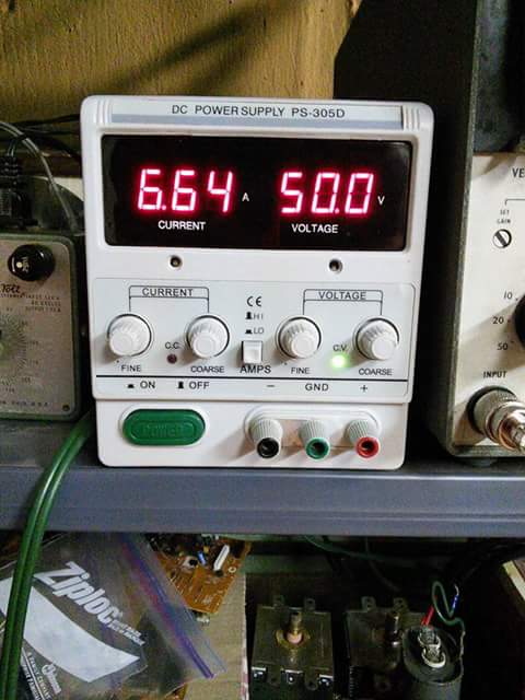
Power supply update: I did buy a fancy looking store bought supply... the results were not good:
Oh dearest brand new Fling Dung Industries PS-305d 30 volt 5 Amp power supply, you died as you lived: somehow blasting out 50.2 volts at 6.66 Amps uncontrollably for about sixty seconds before your capacitor exploded.
Hopefully I'll get a return authorization and lug you to the post office. Seriously, this is I think the first thing I've ever returned to Amazon in twenty years of shopping there. [Update: return shipping from UPS and USPS was more than the refund would be. Do not buy this power source, which is sold under dozens of names. After re-recontacting the seller they sent a free shipping label, I sent it, someone there signed for it and...still no refund].
What! That loud noise wasn't microwave popcorn? Do popped capacitors have delicious salt and butter to lick off? No?!? Meow!