Friday, December 24, 2021

First Handmade Watch Part


Here is the first part I've ever made for a watch. It is a setting jumper lever.


This disengages the gears to let you either set the hour and minute hands, or wind up the spring.


Using a washer as a "finger" to hold the part while filing it. Next project is making a finger vise out of metal for stuff like this. The wavy part that looks like a snake has two cam lobes that correspond to winding or time setting by interacting with a tiny pin.


I cut a triangle out of the washer to gain access for drilling holes. Just like my jeweler's pin bench vise.


Placed into a test watch movement. It works. It's not totally polished, but it works. By machining intricate modern parts I'll gain familiarity and knowledge, which will make it easier to design and build my larger, older style custom watch...which won't be a regular watch at all but a single meteorological complication. But that is way in the future. I've got more machines to build and buy and tools to make, and a rotary gear cutting dividing head to build. 

Eventually this entire test movement will be orangey brass handmade parts. 360 brass and 260 (stronger brass) where I can. I also have some Startett O-1 (oil hardening) steel plates for things that might wear or break immediately...but I want to use as much brass as possible, for no other reason than it'll be an brassy orange visual guide to my progress.


It'll look great orange!

Wednesday, December 15, 2021

Watchmaking Machinary 3: Milling Machine

 Watchmaking Machinery 3 

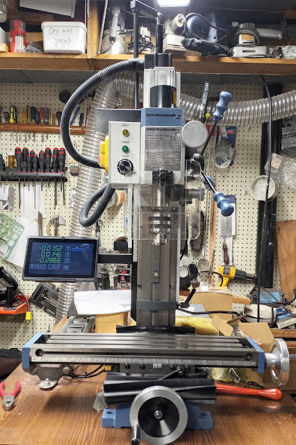
Milling Machine: Meet the beast!


Rational

I chose the cheapest milling machine from Little Machine Shop that had belt drive, and then went up one level to get the version with DRO (digital read outs). That is as of winter 2021 the HiTorque 4190 milling machine. 

It also has variable speed with no gear shifting. The belt drive is quiet and robust. They have smaller machines with plastic Sieg gears that break and are extremely loud. 

This LMS machine has more horsepower, DRO, more work area than the other machine I was looking at: a Taig. The Taig is a very nice machine--and a great deal at half the price! However, I wanted to make large items in addition to watch parts. This meant the Taig was a bit underpowered.

The Taig machine is basically their Microlathe II (which I already own) turned vertical. 

It was a very hard decision but the deal-breaker was this: the Taig machine's Z-axis is controlled by a circular hand-crank mounted on the top of the machine meaning to lower the Taig you have to reach up and crank parallel to the ceiling!!! The LMS machine has a regular pull-down crank like a drill press.

If I bought the Taig I would probably have had to buy a slow, metal drilling drill press to drill holes. With the LMS machine I can use it like a super slow metal drill press, or use it as a milling machine. I have other drill presses, but not a big slow one. In the end I would have probably wanted to do something larger and needed a second mill. 

The LMS machine also has DRO. I like digital readouts for things like, let's say: I have a 1mm wide piece of stock in the vise and I want to make it 0.3mm wide. You can't really dab blue DyeChem and scratch a line at the 0.3mm mark on a 1mm piece very easily. I'd probably need to get another binocular microscope--and the work envelope area of the Taig wouldn't allow that anyway. With the DRO I find the edge, hit zero and then mill to -0.7mm, which leaves .03mm left. Easy!

The LMS machine takes R8 size tooling/collets/etc. You can put much larger tools (end mills) into the LMS than you can in the Taig, which takes ER16 collets. To be fair the Taig is a MICRO (not mini) mill. 

Also, since the Taig mill is literally the Microlathe II turned vertical I already have the capability in my lathe. I have a Taig milling attachment (which is super nice, and inexpensive) for my lathe. That let's me mount and mill things sideways on my Taig lathe. The view is much better that way for tiny parts.

So, I didn't want to duplicate much of what I had. I can lathe and mill on my Taig Microlathe II and use the LMS 4190 for milling and heavier (slow) drilling projects.


Ordering


My order list from Little Machine Shop for the Milling Machine and all the tooling was: 


1757 Space Block Set (for the Sine Bar).

3068 Surface Plate, Granite, 12" x 9" x 3" (heavy, cheap, flat). 

3535 Sine Bar, 2.5", Fisher  (lets you mount stuff in vise at precise angles--if you use trigonometry, made in USA). 

4084 Tooling Plate, 6 x 12" (lets you mount tiny things on mill table, comes with clamps, made in USA).

4190 HiTorque Mini Mill, Deluxe (with Digital Read Outs / DRO).  

4304 Shim Stock Assortment, 0.0005" - 0.005" Plastic  (for tramming/leveling).

4653 Indicator Arm, Universal, 6"   (for tramming/leveling).

4858 Tooling Package, R8 Mini Mill Premium (the best package) .

5868 Combination Square Set, 12" 4R Precision (lets you easily find center of circle/rod end).

5874 Machinist Square Set, 2" 4" and 6" (three L-shaped things).

6258 Clamping Kit, 8 mm, Professional Grade 8-Piece (even more extra clamps for the tooling plate, which I probably didn't need).


6294 Tap Guide, Reversible (I think this was actually for my lathe).

2675 Clamps, Screwless Vise (this was for a little screwless vise I already owned).


Doesn't look like much, but that's 305lbs of stuff. I would have almost doubled the tooling, but I already have a bunch from the lathe. I also got stuff from Amazon and eBay. 

Budget for that: the cost of the tooling equals that of the machine. 

I bought the 4653 universal arm and the 4303 shim stock assortment. They have a package of these two things along with a dial test indicator gauge in a nice cheap set; however-I just got a SUPER nice Mitutoyo dial test indicator, so I'm sticking with that and just bought the other two components separately. This is for tramming (leveling) the milling machine. You measure, loosen the column and place thin shim stock under the column's base and re-tighten. I'm hoping it just arrives perfectly level out to .0001" and I can ignore it. One can hope for lots of things though.

I could have saved some cash by delaying the purchase of the Sine bar and the spacer kit for it. However, that's a lot of weight and LMS ships tooling purchased at the same time as a machine for FREE so I just got everything.

I got the most expensive tooling package for the 4190 Mill. It came with the most stuff. It also came with the best stuff. Machining stuff comes at tolerances/accuracy of: .001" or .0005" or .0001". If figured that if I started off with cheap stuff that is less accurate I'd never do what I want. If your vise and measuring tools and spacers and blocks are all cheap and off more than the best stuff that error adds up...and I need all the help I can get. 

Buy once, cry once for the good stuff. I'd rather buy once and be happy, than at some point have to figure out why I can't get something build correctly--and then realize it's an inferior gauge or vise that's tilted or some other thing. That's why I bought Starrett and Mitutoyo magnetic bases and gauges and surface/height tools.

Shipping


Here is the shipping list with box(?) codes. It shipped a few days after Thanksgiving and they didn't send any tracking email yet.

4190 HiTorque Mini Mill, Deluxe Trk

1757 Space Block Set RRB A1  
6258 Clamping Kit, 8 mm, Professional Grade 8-Piece RRB A1
4653 Indicator Arm, Universal, 6" RRB A1  

5868 Combination Square Set, 12" 4R Precision RRB A2

4084 Tooling Plate, 6 x 12" RRB B2 

2675 Clamps, Screwless Vise Sml FRB  
3535 Sine Bar, 2.5", Fisher Sml FRB  
5874 Machinist Square Set, 2" 4" and 6" Sml FRB

4858 Tooling Package, R8 Mini Mill Premium Std Ctn
3068 Surface Plate, Granite, 12" x 9" x 3" Std Ctn  
 
6294 Tap Guide, Reversible FR Ep
4304 Shim Stock Assortment, 0.0005" - 0.005" Plastic FR Ep  


Possible shipping codes, these are my guesses:

Trk = Tracking? The big crate that is tracked?
RRB = regional rate box?
Sml FRB = small flat rate box?
FR Ep = flat rate envelope? Padded?
Std Ctn = standard container? 


It arrrived from Pasadena to Metro Detroit on the 8th day after it was picked up by the shipping company. The shipping company had tracing (which is just another name for tracking). One morning I got a call from the truck driver saying they'd be there in about 35 minutes. They were!

On paper the mill doesn't sound that heavy, but strapped to a heavy dolly/hand-truck it was a bit scary to take down the stairs to it's new basement home. One person holding it a top and two people down the stairs blocking so it only rolls down one step at a time. 

Lifting it from the dolly to the desk bench it seemed a lot lighter. The dolly turned out to be quite heavy just by itself.

Turns out there were heavy items in with the mill and also the DRO tablet was taped to the bed! Probably should have taken that out before going down the stairs--if nothing else, just to save weight.

We had the crate tipped back and loosened all four bolts that held the mill to the crate floor. I believe they were Allen head bolts that took a 6mm Allen key wrench. We put the entire crate on the table and then took off the front of the crate. Totally removed the four Allen head bolts and just pivoted the mill off the box and onto the tabletop. It was very cold and greasy, so I went back to work to let everything warm up from the wintery truck ride. 


Setup

Day two was wiping shipping grease off the machine (don't start the machine up without doing that!). 

They included a little bracket and 3 screws in tapped holes to hold the DRO tablet. Unfortunately it doesn't fit without a little grinding. The forward facing corner (right side/top) needed to be ground off. 


It's not mentioned in the manual, but I matched the 3 little screw holes with 3 little screws that were already loosely screwed into the left side of the column. THANK YOU Little Machine Shop for pre-drilling and tapping those holes! The plastic hose conduit can knock the tablet off the stand if you lower the head-velcro or a rubber band is needed for safety.


They included the owner's manual for the lesser model, but it's an old manual. It doesn't show what this little lever/knob combo does. Facing backwards the machine turns on. Facing up/down/forwards the machine will turn on but you have to hold the power button down. Also, it makes a horrible clanking noise! 


I think this is a magnetic interlock thing? There is a depression in the spindle that I think clacks against a stop mechanism...but not enough to actually stop the machine from spinning. It's like a safety that doesn't work! Or it's something else? It's not in the manual. I'm not sure how a lock that still lets power to the machine (if you press and hold "ON") is a safety feature. Either the machine is off or on. Having one-and-a-half on/off buttons isn't any safer--especially since the .5 doesn't really do much? I dunno. Would have been nice to put that in the manual.


Here is the machine.


Here it is in the dark, showing off the tablet DRO and green light showing it's on.


Anyway, the four bolts that came with the machine are very nice. However, they are too short to go through the big 2" slab of tabletop I'm mounting this machine on.

I used a Wixey digital level and a couple spirit levels and got the bench top leveled. Then I leveled the machine with the levels on the XY table. Left to right the XY table is at 0 degrees level: perfect! Front to back (if the machine was falling toward or away from the user) the machine is 0.1 degree level: almost perfect. To be clear this is the entire table top and entire machine--this is NOT the tramming of the mill's column. That's way more precise.

I have drilled the 4 mounting holes to attach the mill to the benchtop. Just waiting to get four longer bolt's: 3" long threads instead of the 1 3/4" shipping ones. I'll reuse the nice washers that came with the shipping bolts.

Shimming

I shimmed the left two bolts on the column to bring the left/right table level.

Then I added shims to both the front column bolts to lean yhe the column back (to reduce the "nod" of the head).


I used the Little Machine Shop shim set. Thicknesses weren't labeled on the package.

I got the right to left table to .001" and the front to back .002" which the manual says is good. It takes a lot of bting and unbolting the column screws. Easy but hard, like walking 50 miles: step by little step.

The vise. Enraging: to mount the big swivel vise you throw away the huge bolts that come with it and use the (pay extra) vise mounting bolt kit.

They tell you that you can't use the swivel mount. Hmmm... Then why did i pay so much extra for to he swivel base vise?!

All you have to do is ditch the tiny washers and cut and grind the threaded rods in the vide mount kit down.

You will end up with less than a .001" clearance between the top of the nut and the bottom of the vise, but it will swivel just fine.

Cut with a hacksaw, then grind a little.


You  can't even see light between them but the vise is mounted and it can still swivel!


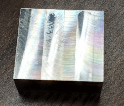
...and here is the culmination of 3 years of research, planning, procurement and setup: a mirror smooth milled channel. Done with a 2 flute roughing end mill (too slow pm and no coolant, lol).


Beautiful irridescent and smooth.


Wednesday, November 10, 2021

Watchmaking Machinery 2 DRO Cross slide


I ordered a digital caliper DRO (digital read out) for the cross slide of the Taig lathe off of eBay.

Well: it was stuck on its bracket with tape; the tape pulled the back caliper sticker off and the anchor point tape came off too; the bracket was some purple transparent 3D print stuff that was less rigid tha PLA; also the anchor bracket had a twist which caused the slide to bind.

The calipers had the measuring jaws cut off. That was the only good thing-other than the whole thing was a sort of inspiration template for me.


So I cut an aluminum block into a "C" shape with a drill press, hacksaw and jeweler's saw to connect the drilled holes.


Then i remembered I got my bandsaw running straight (by twisting the table and adding more tension). So I popped a bi-metal blade with tiny teeth on it to help with the rest.

I made the anchor point with a drill hole that was also counter sunk most of the way down. I didn't go all the way down so the part of the hole that narrows down would grab the head of the screw and keep it from pulling through when i tightened the t-nut (which is just a screw and tiny nut).

The Allen key wrench is on the screw in the photo. Then I bandsawed the top quarter of the tiny anchor off. I then drilled two screw holes in a bracket and the anchor pieces, paying careful attention not to go down the center so I wouldn't interfere with the Allen key wrench path.

When tightened, the two halves trap the end of the calipers. As the cross slide moves toward or away from the operator it pushes or pulls the caliper slide which measures the movement to .01 of a millimeter. You can also hit a button and it displays inches.

Anchor point is solid. The plate over the caliper slide end is raised, because it's acting as a clamp. Standing normally it isn't apparent to the operator, and looks pretty cool.

The big C-block is super sturdy. A screw feeds up from the bottom to a nut that is in that T channel.


A single screw holds it to the block. This allows it to pivot counterclockwise for installation and removal. It also allows me to make sure the slide is perfectly parallel to the carriage and slidebefore tightening the anchor point at the other end.

The C-block is most of a 1" x 2" x 4" bl9ck of aluminum. Much, much stiffer than the 1/4" thick 3D printed plastic bracket which visibly flexed.

My C-block doesn't move. Sliding out and returning to starting point gives me a repeatable readout of "0.00mm". You don't get much better than zero-hundredths of a millimeter.

Watchmaking deals with 0.3-0.8mm (tenths), which is much larger than 0.01mm (hundredths).

Meow² 


Saturday, October 30, 2021

Watchmaking Machinery Part 1


Watchmaking Machinery Part 1


Here is my new Taig Microlathe II with a binocular microscope attached to it. 

The microscope is a Swift 2x/4x mounted on an arm that I made out of plate steel and aluminum tubing. It has an LED illuminator and almost the entire microscope is made out of metal!


Taig lathes are still MADE IN AMERICA and are extremely high precision instruments.


View through the microscope at 2x:


Actual size view:


The microscope is removable for safe keeping. I mounted the lathe onto a filecabinet drawer type thing and filled it with the accessories: milling attachment, tools, measurement devices, etc.


The initial order to Taig was for:

1017#3 Starter Set #3 - Base + 5C Headstock       

1096 Unground tool bit 1/4" square       

1170 Extra Tool Post       6             

1171 Back Tool Post        2             

1110 Slitting saw arbor                 

1232 1/4" Diameter Milling Cutter           

1230A 1/16 dia Milling Cutter    

1230C 1/8 dia.Milling Cutter      

1111 Hi Speed Slitting Saw          

1152 Die Holder for Tailstock     

1224 Fly Cutter

1210 Radius Turner        

1038 4 inch swivel joint tool rest (wood turners)

1190 Steady Rest            

1225 Milling Vice             

1173 T Bar Cutoff Tool  

1200 Top Slide Mounts  1220 Milling attachment              

300-82 (T-Bar Cutoff Mount)      


Tons of other tools, bits, bit steel to grind my own cutters, calipers, dial indicators, raw metal stock, etc. are on their way too.


The first learning goal is to take an existing watch movement and replace it piece-by-piece with pieces that I manufacture. Replacing steel with brass, until I've made a complete movement. See you in a few years...


The chosen movement is an ETA 6498 M03 that was introduced in 1950. It's a pocket watch movement. ETA's website is awful and always down for service. If you need the tech specs for this movement do a search for "'CT_6498-2_FDE_482480_08" and there will be a few results.


Saturday, October 2, 2021

Halloween 2021 Pumpkin Contest


Halloween 2021 Pumpkin Contest @ work


Old defibrillator, IV bag + stand, and a red pumpkin. 

I can't decide whether to call it "Mama told me to make some friends, so I am" or just "I heart Halloween".

I put veins on the red pumpkin with some hot glue gun glue. That worked out well. I had a jammed glue gun and was spraying the glue onto a paper towel to unclog it--then I realized it'll be better to put that on the pumpkin. 


Sunday, September 19, 2021

Supra Advantage Express II real estate lock opened

 Supra Advantage Express II 

Real Estate Lock Opened 


These locks have: a big shackle to attach the lock, and a small drawer that opens and gives the real estate agent a key to the house so they can show it to potential buyers.   

These locks are digital, and though they have a removable keypad you need to update a PAID subscription service to get the keypad to actually interact with the lock. There are cool reporting functions (what agent got the key out, when they did, when they put it back, etc.). 

I have the manual, the keypad, a new odd battery for the keypad and the actual lock. No good. This is a bypass...with a hammer. 

 The lock still functioned (locked) afterward and I can do this over and over and still lock the shackle. It take a good wack or three on the side of the lock, near the top to open the shackle because it is spring retained. 

I was using a lead hammer, but one of the transparent yellow plastic headed hammers would probably work better since you're trying to basically vibrate the metal components against the spring tension to pop it open. 


Below is the mechanism for the house-key compartment at the bottom of the Supra Advantage lock. 


It is basically two metal pins (on at each end) and a winding of red lacquer-coated magnet wire. Power (probably 12 to 24 volts DC) goes through the wire and it pulls in both pins. That releases the little drawer in the bottom of the lock so you can get the house key out. 


Here is video of just about 9vDC making the pins go in and out. Higher voltage would make them go inward farther/longer time allowing the drawer to spring open.


This little drawer can be defeated by hitting the lock, near the bottom (but on the side) with a plastic headed hammer. 


One of those with the transparent yellow heads. This can for the pins (and the springs that hold them outward/locked) to jiggle around and the drawer will fall open. Or it will jam. 

There are 3 hollow split pins at the bottom edge of the lock. All those do is keep you from slamming the drawer too far shut. They have zero value when physically trying to break the lock open.

Sunday, September 5, 2021

Micro Precision Drill Press Watchmaker Drill Press


So, making wristwatch parts requires teeny-tiny little drill bits (0.3mm). For fun I took my mini cylindrical drill, a drill press stand and a magnifying LED light with clamp and made my own micro precision drill press.


I shopped around: a USED micro drill press is close to $8000. A crappy one is $350. This cast iron beast was way, way, way less than all that.


Feast your beady little eyes on my sub-millimeter hole shooter (explanations after the photos):


This stand is fantastic. I added a "micro drill" to it instead of a corded drill. This is for micro drilling. I'm using drill bits with diameters of LESS than a millimeter usually. Watchmaking 0.3mm to 2.4mm bits usually. Some of them are literally thinner than a human hair. Most people buy these for CORDED drills with clamping collars (i.e., most corded Milwaukee, Metabo and Wen drills).  


This stand is VERY heavy for its size due to its cast iron base (I checked it with a magnet). The magnet stuck to all the green parts. The magnet did NOT stick to the yellow part (the moving dovetail part of the head and the drill collar clamp part). The magnet also stuck to the actual column, meaning it's steel and not aluminum. The rotating part of the head is green and steel. I'm not using that function, but it's still nice. 


The jibs (part that the dovetails rub against) are replaceable copper strips. The dovetail tightness can be adjusted by screws. Yes, you can fine tune this thing just like a lathe or milling machine. That simple thing is a HEAVY DUTY feature in any machine.


The spring is fairly hard to pull down without a drill in it. I'm assuming once you put a heavy corded drill in there it will pull down easily. My cylindrical drill is very light comparatively--so there is a little extra pressure needed. Although it's not bad. If it was a problem you just unhook the bottom of the spring, and pull it up out the top and replace it with a weaker (or stronger) spring to suit your taste. I'm just happy that the flat pinion rack (flat part of metal that engages with the gear when you pull the lever down) is nice and smooth. VERY smooth.


Here's a tip: if you don't want to bolt this to a bench top you can bolt three rectangular blocks of wood to the underside of the base. The left/right support the press on a table/shelf for storage. Then when you want to use this thing you clamp the center block of wood into a vise. I have that on some mini-vises that can clamp into bigger vises like Ukrainian nesting dolls. LOL! Anyway, YOU NEED TO CLAMP/BOLT/SCREW this to a work surface--it's not super tippy, but when you pull down on the lever it will be. The base has holes in tabs in all four corners (plus one huge hole in center). 


When open the circular hole that you clamp on your drill collar is 43mm. My cylindrical drill has a diameter of 40mm. I needed one of the (three or four) plastic sleeves they give you to assist clamping smaller collars. That 3mm thick sleeve really made a difference. 


In my photos I show a 1mm drill bit in my drill--but shown through the magnifying lamp I added. My intention is to add a wooden base with a couple drawers for tiny drill bits--and then mount the speed control for my drill (0-13,000 RPM) to the LEFT side of the cabinet. That way I can adjust the drill speed with my left hand while pulling down with my right.


Things I would change:

It comes with FOUR Allen key/wrenches because they used FOUR different sized Allen bolts. One of the keys only fits the bolt for the arrow pointer head thingy on the depth gauge. It doesn't matter to me, but they'd have to buy/store/track 1 less bolt size, 1 less nut size, and give away 1 less Allen key if they just settled on THREE sizes of bolts. They could probably just use TWO sizes. 


The depth gauge has "6" at the top and "0" at the bottom. That means as you pull down on the drill your depth gauge is reading backwards. A two centimeter deep drilling hole goes from 6 to 4--instead of 0 to 2. I've seen that on other tools, and it's annoying.


The cap on the top of the column has a little hook for the drill power cord. It's very open and the cord can fall out. No big deal, it's probably loose so the cord doesn't catch and the drill moves down--but maybe a "V" shape that contains the cord and let's it move rather than a "C" shape that lets it fall out. With that said, my drill cord and my magnifying light cord seem pretty happy--and I can always zip-tie them loosely if need be. 


Why did I do this when I have other BIG drill presses, lathe, etc.? I'm playing around with a couple of wristwatch movements and wanted to drill REALLY small holes. I started looking at tiny drill presses: garbage plasticy ones for $80; garbage plastically ones for $350; nice ones at about $1000. Really nice ones up to $15,000. Yes, the price of a car--for a teeny tiny drill press. Look up used "Precision drill press" and you'll be amazed. No thanks.


There is a somewhat similar drilling stand which looks cooler (all steel) but it looks like it has rack and pinion metal-strips pop riveted together as it's movement mechanism. Lots of sideways jiggle and non-repeatable drilling (can't hit the same hole twice). No thanks.


To be clear: the magnifying light and cylinder micro drill DO NOT COME WITH THIS THING.


Anyway, I would go this route versus a sub-$1000 precision drill press. Anything under $1000 is going to be trash. Make your own setup with this.


M1K3 FR0M D3TR01T