Seeing NFC with Oscilloscope
In the last post (https://michaellogusz.blogspot.com/2019/03/wireless-power-transmission-to-make.html) I showed a smart card reader.
This smart card reader sends and receives 13.56Mhz signals for Near Field Communication. To test it I put a little LED chip that lights up by harvesting 13.56Mhz energy.
I wanted to see these waves on my oscilloscope. I found one super simple way to sniff NFC signals and another that was almost as easy.
The first thing I did was plug my RFID smart card reader thing into a cell phone AC wall charger outlet. Luckily, that made the card reader constantly send out a continuous NFC signal. This way I didn't have to hook it up to a computer and keep clicking "read" to get a signal. Nice!
Next I turned my oscilloscope probe into a signal tracer antenna sniffer loop. How did I do this? I clipped the alligator ground clip to the tip of the probe. That's it! Oh, I also set the probe to 10x instead of 1x. That's not a big deal, but the readout on screen looked nicer, because I had the scope set to 10x for no particular reason I can recall.
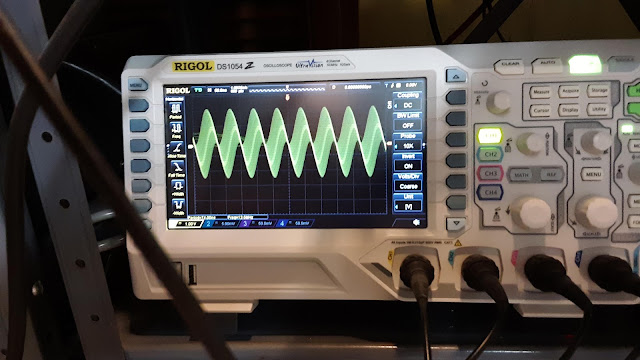
Anyway, then on my Rigol oscilloscope I clicked "Clear" button and all of a sudden all 4 channels came on. I shut them off one-by-one except for channel 1. I must have had some weird settings leftover from last time I was playing with it, because after seeing nonsense information all of a sudden I was treated to this:
Big waves with tiny little waves jiggling around inside them. If you look at the center of the photo you'll see toward the bottom "Freq = 13.7MHz". This would constantly go from 13.56MHz to slightly above and below. There was my Near Field Communication signal from the card reader right on screen.
Then I thought, what if I used an actual antenna made for NFC--instead of my home made loop? So, I fished around in a junk drawer and phone a broken phone I found in the garbage that had an NFC antenna. This antenna is pictured below. It's actually technically not an antenna: it's an NFC and wireless charging induction coil.
As you can see by my drawings I took a multimeter and did continuity tests. It turns out the little copper connection boxes (which I arbitrarily numbered 1-7) aren't all connected.
Boxes 1, 2 and 4 connect to each other.
Boxes 3 and 7 connect to each other.
So, I hooked my oscilloscope probe tip and ground clip up: one went to 1 or 2 or 4; and the other went to 3 or 7.
When I slammed this induction sniffer onto the card reader I got a way cooler looking set of waves and the frequency readout at the bottom of the oscilloscope screen read 13.56MHz most of the time.
In this way I sort of proved that the smart card reader was putting out 13.5MHz waves, but also that the phone induction coil wasn't just self-resonating at 13.5Mhz: because my crappy sniffer loop in the first part of this experiment also gave me 13.5MHz.
If you have an oscilloscope that's 50-100Mhz you can do this too. However, older scopes that don't go up that high (I have many scopes that are under 10Mhz) won't show you 13.5MHz waves. I think you're supposed to have an oscilloscope that is rated about 5 times the signal you're trying to see. Theoretically, my oscilloscope would be just under this...but it still worked.
If you want to do this the correct way, you'd by a $9000 spectrum analyzer or one of those cool hand-held "RF Explorer" boxes that go up to 6GHz (GIG! not Meg) so like 6000MHz. RF Explorer has units that are weirdly advertised and named so you think you're getting a certain range of frequency, but it's not really that range. For this I think they have a model that's only $180 that would do the trick, for a little more you can get a 2.4GHz model to play with Wifi signals (but I don't think that model can go down to 13MHz. The RF Explorer units range from $120-$500 and up.
The best thing they have is a signal generator that can go up to 6GHz. I thought about getting one of those for doing this same stuff with WiFi signals, but my oscilloscope can't go up to the Gig range (only MHz). Then I came up with an idea: the router I used for my last post about lectennas puts out 2.4 and 5Ghz signals: just plug an ethernet cable into one port and then into another of it's output ports: create a loop back into itself: this creates a packet storm and plenty of WiFI waves flooding the room. This might also be a way to stress-test a WiFi system, lol: no anechoic chamber and spectrum generators needed.
Anyway, after clearing the settings the frequency stopped bouncing around from 60-100Hz and went to 13.5MHz, and cool waves appeared. Not sure why that didn't happen until I hit "clear" on the oscilloscope. Keep fiddling with buttons and sometimes stuff just works out!


