Showing posts with label vacuum tube. Show all posts

Saturday, June 2, 2018

Easy Way to light magic eye tube EM80


Easy Way to light magic eye tube EM80


This is a green glowing EM80 tuning / indicator / magic eye tube. I just wanted to see it glow. I was able to make the glowing green fan shape slowly open and close. They make (made) round ones called "cat's eyes" that wink! These were cheaper to make than moving needle meters, but as you can see from the Geiger counters in old monster movies, needle meters grabbed hold way back in the 1940s. Luckily the failed and demented priciples of socialism in the USSR kept factories producing these tubes in Russia until the 1990s...instead of food or clothing or useful items...they just kept making these tubes that the entire world (including Russia) atopped using in the 1920s! For under $20 including shipping on eBay and Amazon you can still get brand new in box magic eye tubes. 

See the bottom of the page for a video of my capacitance tester that has one.

AC/Furnace and power supply were making a lot of noise in the video. I was also nervous about holding a camera and live wires--so it's loud, weird and shaky.


Here is the stupid simple way I got it to light up, and then open and close:

+250vDC to pin 9
+250vDC to 470k-660k resistor to pin 7

-250vDC to pin 2

5vDC wallwart either output to pin 4
5vDC wallwart either output to pin 5

Touched pin 1 to pin 7 momentarily to work the eye.


When I touched pin 1 to pin 7 the eye closes, but 250vDC power supply sags. I'm only doing it for a few seconds at a time. The grid voltage (g1) on pin 1 is supposed to act to choke off the power to the tube's triode to open/close the eye. It's supposed to be like -1v to -14v, but by connecting the pins I'm hitting it with almost the full -200v I think.

It worked better with a resisitor higher than 220k. Added second 220k to give 440k and it worked but still got too dim when working the eye. A third resistor made it 660k and that seemed better. That's what I uses in the video. I built a decade resistance box which I'll plug in, and then turn dials to easily set different amounts of resistance and see what works better.

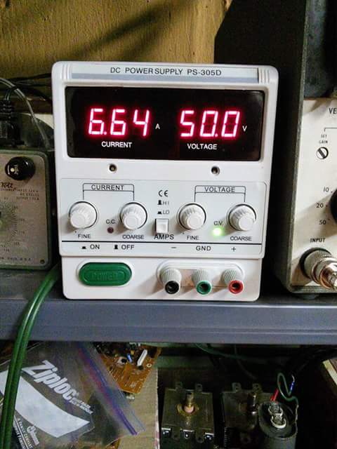
My big DC electrophoresis supply was set at only 200vDC in the video: still utterly deadly!

Anyway, the drop in voltage in the power supply is either: supposed to happen (triode shutting down due to control voltage); or it's not a great idea to basically short out your power supply. Most power supplies might pop a fuse/capacitor/blow up, but I was using an electrophoresis supply which is meant to have wires dangling in water/gel for DNA testing...so it might be a little more forgiving.

Here's the schematic:


Here is the replacement of the resistors with my decade resistance box:


I discovered something nobody else online has mentioned: if you use a resistor (or dial up resistance on a box) at 10k you will see a faint ghost image of the open/closed positions on the eye. If you turn the 10, 000 dial right or left you will see these lines move. When you touch pin 1 to pin 7 the lines will be where the eye opens to! Its like a preview! I call these "Logusz Lines".

Here's a photo of my Heathkit DR-1 decade resistance box I bought for a dollar at a resale shop. Heath Inc. used to be nearby in Benton Harbor Michigan.


Extra notes:


All of my posts are just lab notes online. Most are deadly projects! These are not instructions!


Crazy deadly mess of wires. On the left are two of the eventual three resistors in a row. The red wire is +250vDC which splits off: one way goes directly to pin 9. The other goes to 660k resistors which goes to pin 7.

So, what if I put a potentiometer between pin 1 and 7? With it closed it would have to dissipate a lot of power (heat) and possibly melt. I'm not sure if I'd have to ground it (using 3 wires) or not (using 2 wires). Which way would kill me or the circuit?

What if I put a decade resistance box in place of the resistors at pin 7 and dialed it up and down? Power (heat) dissipation wouldn't be a concern, since it wouldn't be connected--only when I touched a wire from pin 1 to 7. This is a great way to dial up a different resistor value without having to solder in/out a bunch of resistors. I had different results with the 3 different values I tried (220k, 440k and 660k). Different amount of eye open/close but also dimming of the entire green output.


Here's the original report: just wires and no resistor so it would glow green:

Here is the pinout for the EM80 tube:


Nothing will happen without a power supply going to the heater pins.
You must add around +200vDC to pins 7 and 9 and -200vDC to pin 2 to get green glow.

To begin:

I needed a 6.3v (AC or DC) supply for heater pins 4 and 5.

I found a wall wart phone charger type thing and cut the end off and attached the bare wires to yellow alligator clip wires. On the wall plug part it had a sticker that said the output was 5 volts DC. Close enough!

I plugged it into the wall and the heater filament inside the vacuum tube gave a tiny orange glow. Success!


Next I needed 250v DC power. This had to be DC.

I was usiing the nifty disposable camera power supply I made for my neon bulb post. But then my 250v DC laboratory electrophoresis power supply ($65) arrived from eBay. So I used that.


As noted in my neon lamp bulb post high DC voltage is very hard to come by: either a camera flash diy conversion, a lucky find on ebay, or splicing wires into a guitar amp or old time tube radio. Lighting up to see the green glow is fine with a camera flash conversion, but I think shorting out to open/close the eye would kill it.

I took a white wire and ran it from the POSITIVE 250v DC output to pins 7 and 9.

Then I ran a green wire from the NEGATIVE -250v DC output to pin 2.


Boom: crazy green glow! So happy.


In the datasheets and magic eye tube tester circuit diagrams the ground symbol actually means the negative DC wire from the DC power supply. A DC power supply only had two output wires: positive and negative. By an annoying convention ground can mean the negative wire of the power supply or battery you're using.

The spec sheets comes right out and says AC or DC is fine for the heater pins, but they don't make clear that the 250v supply needs to be DC.

To get the green "eye" to open and close you can sometimes short certain pins together. To slowly open and close the eye the proper way is to input NEGATIVE -1v to NEGATIVE -14v. I do not yet know if that is AC or DC or if it's relative to the 250v DC? Like: is it -1 volt or 250-1= 249v?

Also pin 1 is the control grid pin. How do you add voltage to a single pin? Some specs seem to show positive and negative wires going towards that single pin. If it's wired in how do you raise and lower the voltage to open and close the eye? Add a potentiometer?

Supposedly, if you ground the control grid the eye will open. Give it negative volts it will close. This is "biasing" the tube.

Without any resistors Connecting pin 9 to pin 1 turns off the green. That makes sense because pin 9 has the full +250vDC and pin 1 (control grid) wants negative DC. It seemed like a bad idea to continue testing this. I won't connect pin 9 to anything anymore. I'll just unplug everything if I want darkness.


Here's more "official" ways to open/close the eye, but I haven't tried them yet, mainly because I don't have an old timey radio with an AVC (auto volume control) to feed into pin 1.


Here is my Sprague capacitance tester that has a round "cat's eye" magic eye tube:


Sunday, September 25, 2016

Homemade X-Rays From A Vacuum Tube


Homemade X-Rays From A Vacuum Tube


In the electromagnetic spectrum, X-rays are between ultraviolet and gamma waves, but there is some overlap between the x-rays and gamma waves. Simply speaking, the difference between X-rays and gamma rays is that: 

Gamma radiation is produced by nuclear decay of radioactive atoms.

X-rays are produced by electrons banging into metal.

Except for their source, there is basically no defined difference between the two. They're just photons, like all electromagnetic phenomena. Photons have no mass and no charge. They are light itself. I've played with gamma radiation already using my mineral collection. To experiment with x-rays I had to make them myself. So I did! 


How did I do it? Easy! 
I found an old vacuum tube with a metal cap on top.
I took a multimeter set to Ohms and touched the probes to each pin. The two pins that gave any reading were the heater pins.
I took the output wires from my high voltage source and connected one to the metal cap and the other to one of the heater pins.
Turn on the power to over 20, 000 volts and a purple glow inside the tube made my Geiger counter go wild! 
My power source was a $9 3.6v-6v to 400, 000 volt boost step up power module high voltage generator from Amazon. I could have fed it with two AA batteries, but i just used the Elenco power supply I built to give it 6v DC input.
The tube was $1 at a local antique shop. I have a bunch and only one produced a lot of x-rays. The first one in the video was actually the only other one to produce x_rays, although rather weakly.

Instead of a power source to power the step-up boost transformer, two AA batteries would work fine. I used it to give 0-6 volts DC input into the boost transformer at up to 1 amp. Then I used the 3 amp outputs and the purple glow inside the vacuum tube grew intense, but so did the internal sparks and noise so I don't recommend it.

Here is the setup:


Here's the spark gap without the vacuum tube in between the wires.


I have a photographic darkroom, so I'll eventually get around to x-raying things on top of film plates and developing them. 

About the metal cap at the top of my tubes:

The metal top cap connects to one of the electrodes, the other electrodes being connected to the tube’s base pins. There are a few uses for the metal top cap seen on some vacuum tubes: sometimes it’s used as the anode, which means it’s more robust and can handle higher voltage. They run the highest voltage through the metal cap so it’s isolated this way. 

They also do the exact opposite: sometimes a very low signal was sent through the metal cap for control grids. 

So, either the metal cap can be the HIGHEST most dangerous voltage-or the LOWEST safest voltage that you may actually need to test

It’s a real gamble. You might fry your meter or even get electrocuted. For my uses I ASSUME that the metal cap is the anode and blast it with high voltage to produce x-rays. I touch NOTHING and if the tube blows I don’t really care. In my case my meter makes no physical contact since it’s a Geiger counter. Back in the “good old days” you could tap your finger on the metal grid control cap and hear it on sound equipment…of course if that control cap turned out to be hooked to the anode you wouldn’t have a finger left. ZAP!


Above is a video of my newest tube: the infamous 2x2 which gives off massive amounts of x-rays. It doesn't seem this matter which pin I fed the high voltage to, the result was lots of x-rays.

Friday, August 7, 2015

Bench Top Laboratory Power Supply


Bench Top Laboratory Power Supply


I was going to buy a bench top power supply, but I wanted to build one on my own to learn about them first. So I soldered together an Elenco XP-720 AC/DC full-wave rectified 15v negative or positive DC 12.6v AC center-tapped 1 Amp supply with 3 Amp at 5v DC power supply.


That's a heck of a long name, and I wanted to learn what all (at least some) of that meant. I learn by doing. I'm not one of those people who go around saying, "you should..." or "somebody should..." do whatever. I do what I do.

One thing I don't do so often is solder. It's been a while, so I soldered up my last project to practice. I still have the soldering iron my father gave me when I was ten years old. Although more and more solder is the horrible lead-free type. 

And now a brief rant about solder that you can skip:

Lead-free solder is poisonous to the person using it.

Leaded solder is not poisonous.

Lead vaporizes at 1100° F, which is way higher than the temperature it melts at. You will encounter zero lead fumes while soldering. This is a scientific fact you can easily research yourself. Weller is a company that sells fumes extraction safety devices and even they say the lead isn't the issue, it's the flux (more on flux below).

Lead-free melts at a higher temperature (making work less well), spits hot droplets more to burn your arms, and gives off terrible fumes. It also is porous, meaning even if used properly if will fail way sooner than lead solder. It also is more brittle. You will risk your health to build an inferior item for the benefit of...?

The governments of the world want to protect theoretical people who don't exist from drinking well water on garbage dumps from having old electronics in land fills somehow leach lead into the water...but wait, they wanted to ban plastic bags because no water or air gets to them in landfills to decompose them?

They are poisoning solderers to protect people who drink water from garbage dumps.

The safest choice for solder in your home is lead.

The most dangerous part of any solder is the flux in it. It's made from pine tree sap and breathing the fumes (or even having the fumes contact your skin) can cause a long list of dermal and breathing problems because those fumes contain formaldehyde, hydrochloric acid, all sorts of benzines and toulines and phenols that are just bad, bad, bad. Yes, the trees are killing trying to kill us!
Any way, the future of solder is MesoGlue!  MesGlue is as nanotechnology were there is a jagged piece of Indium. When this is mated with a fitting jagged piece of Gallium it liquifies without heat and creates a solder joint. I love Gallium, it's my second favorite metal, next to Bismuth. Gallium feels like lead, but if you hold it in your hand it will melt!!! Just like liquid Mercury. I have some, and it really melts in my hand. Magicians make spoons out of Gallium, then dip then in hit water to make then disappear (disolve).

Your reward for reading that rant: a nicely laid-out soldering station design:


Here is my messy soldering on a circuit board. I solder wires together all the time, but that's easy: weave the wires together and heat. Apply the solder to the wires, not the iron. You have to be quick for diodes and such-heat can damage them and they're really, really tiny!

You'll notice my 40 year old soldering iron tip is grungy. After this I cleaned it the way you're not supposed to: sand down to the copper, plunge it while hot into plumbers flux (which shouldn't be used with electronics) and add high tin content solder. Tip gets a mirror finish in just a few seconds! All over the internet they say not to expose the copper of the tip, however if you talk with people who use soldering irons for a living they say that if they run out of tips they just jam a piece of thick copper wire into their iron and get to work!


Clipping the excess is easy with diagonal cutters (some call them "dikes" for DIagonal CutterS. I got these Italian made Hakko CHP-170 ones off Amazon for $3 with free shipping!  I wish I had these 30 years ago, they're so good I can't tell the difference between closing them empty or actually cutting excess circuit legs/posts/leads off after soldering.


Here are some lovely diodes that only work when the input power is positive (AC current alternates). One diode gives half-wave rectification so there are two per output. 2 x 60 cycles in US household AC equals 120 cycle output. Full-wave rectified.


The big cylinders are capacitors. They're kind of like batteries. They store current and release it smoothly: making crazy alternating current (AC) into pleasantly stable direct current (DC). There are many here for the various choices of output.

Dead center is a little black half cylinder that is an integrated circuit. It's part of the regulation for the 5v 3a output. It's keeps things really stable: if there's a voltsge drop this drives it back up to 5v. On the Amp side of things, if more than 3a is coming in the grey tube at bottom center shunts the excess to another integrated circuit which bounces in a look to the first one. This will overheat and shut down, which is better than overheating and catching on fire (but I got close, more about that later).


Speaking of outputs: here is a view of the binding posts from inside the box. Black is common/ground/true-earth ground/floating ground/negative depending on how you set things up (if you want to start an argument, just ask what these colors "officially" stand for in AC and/or DC applications). Red is positive output. Yellow is more positive outputs of AC, except one choice here is for negative -15v DC, so I have no idea what that qualifies as when operating in that mode.


The wires are for routing all the lovely electrons through this machine (yes machine: it can change AC to DC and/or vary Amps and Volts, and double the cycle rate of regular household electricity). The big white thing is just the transformer, which we've discussed in previous posts.

Although this transformer is center-tapped: instead of two wires coming out of it, it has seven! This allows you to connect one part of the coil and get half AC output, or connect in to the black post and get full 12.6v at 1a AC output (which might be why it's binding posts are yellow, like the negative DC). Simple, yet fancy.


17.8 Volts at 1 amp. Enough to kill. 
It's the Amps that kill. 1 is enough. 

17.8v x 1A = 17.8 Watts.

There is another output that outputs 5 Volts at 3 Amps. Even though that's only 15 Watts, the 3 Amps is enough to kill you three fingers over!


Here I have the positive (+) DC knob turned all the way up, giving me 17.8v at 1a DC.


On the left is my nicer multimeter that I bought to protect my 40 year old one that I love. The one on the right was only $3 and works great. I bought a few to use in situations where the multimeter might be damaged.


The expensive one has a thermometer! That drink isn't cold enough...


...but the $3 one has a built in transistor testing jack!


Most importantly, the expensive one can measure capacitance.

The expensive one also is auto-ranging, while the cheap one is manual. You have to pick the Volt or Amp range of the circuit your testing. Pick the wrong one and zap! Everything in electronics is crazy decimal places that are all abbreviated with k and m and M so it's easy to confuse ten volts (10v) with ten-thousands volts (10kv) when squinting at a circuit board.


Speaking of damage: below is a 10uF 25v capacitor which I blew up, literally! Pop!

You see, firecrackers are rolls of paper with gunpowder sprinkled inside. Capacitors are rolls of paper with oil sprinkled inside. Can you tell where I'm going with this?


To get full 12.6v power you connect a yellow post to the black. I connected yellow to yellow on the wrong (DC) side and bang! Shreds of paper all over the inside of the box. It was very loud. So I spent $5 and got 100 capacitors off Amazon as backup. It could have been a deadly mistake: wrong color and wrong side. This is why I don't go mushroom picking.

Now I have a ton of new knowledge about electricity and my very own power supply for further experimentation.


So, what's the first thing I did with my power supply besides testing? Lighting up an old vacuum tube. I put red marker on the two heater pins, which I found by using a multimeter on Ohm/resistance setting. These were the only two that had an actual reading. These two pins were, by the way, totally different than the two different schematics I found online!


I ran two power cables from my power supply. Since this is a Tung-Sol vacuum tube with a part number "6K6GT" I knew the heater takes 6 volts. The first number 6 is the one that tells you the voltage. Other tubes use 12v and thus have a 12 as their first number. I first tried 6v of DC power, but it only glowed with a barely visible pin point. I raised the voltage to 8v and it glowed more, but I was afraid of blowing the tube.


It wasn't super bright, like some tubes, but I did glow better when I hooked it up to my power supply's fixed 6.3v AC outputs. AC worked much better than DC.


Power supply update: I did buy a fancy looking store bought supply... the results were not good:


Oh dearest brand new Fling Dung Industries PS-305d 30 volt 5 Amp power supply, you died as you lived: somehow blasting out 50.2 volts at 6.66 Amps uncontrollably for about sixty seconds before your capacitor exploded.

Hopefully I'll get a return authorization and lug you to the post office. Seriously, this is I think the first thing I've ever returned to Amazon in twenty years of shopping there. [Update: return shipping from UPS and USPS was more than the refund would be. Do not buy this power source, which is sold under dozens of names. After re-recontacting the seller they sent a free shipping label, I sent it, someone there signed for it and...still no refund].


What! That loud noise wasn't microwave popcorn? Do popped capacitors have delicious salt and butter to lick off? No?!? Meow!