Sunday, February 14, 2016

Glider & Dethermalizer Timer Build


Glider & Dethermalizer Timer Build


Day 1 building a Georgia Swift 19 balsa glider and a dethermalizer timer to release an airbrake flap. The flap is needed because this type of glider can catch a thermal draft and stay up for ten minutes or longer. The timer will release the crash landing flap after about a minute so the glider doesn't fly away forever!

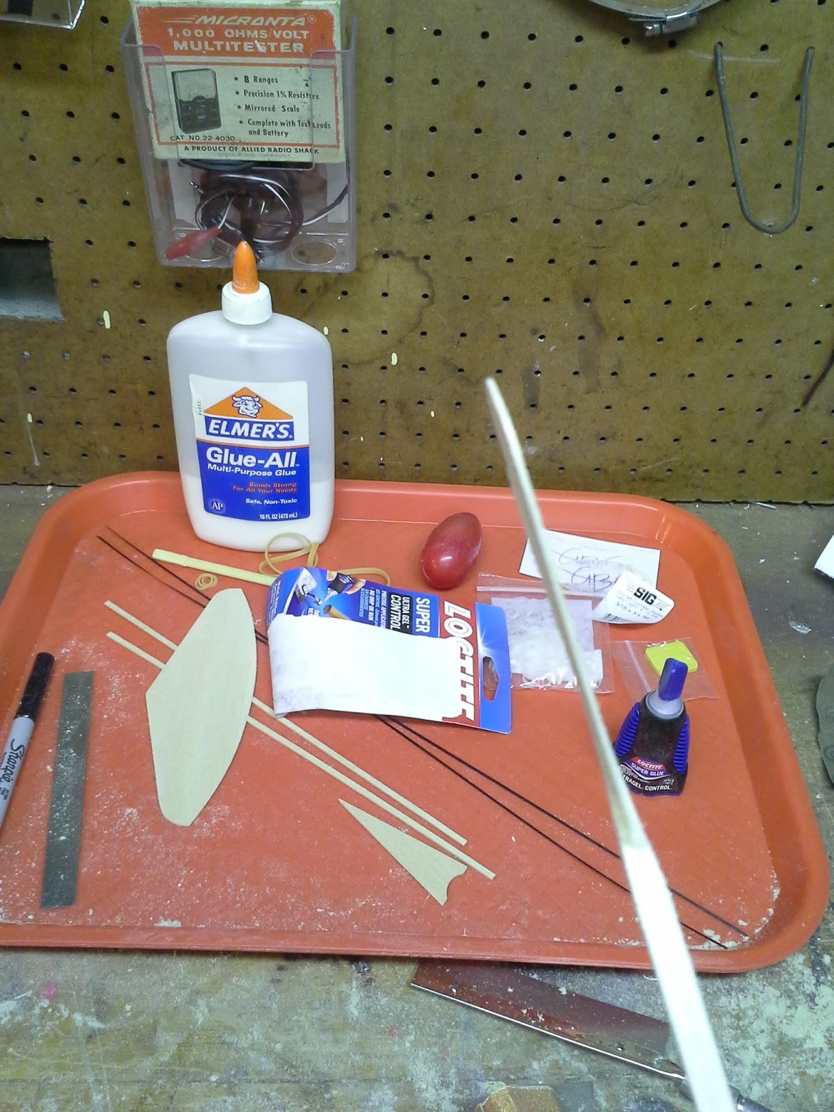
All the glider parts, and extra stuff (like Silly Putty!) for the dethermalizer timer. I went with Loctite CA glue instead of Elmer's. The Loctite is like Crazy Glue, only it's a little bit gel-like in consistency, instead of watery, making it easier to apply without running everywhere.


Here are the wings, boring and flat. I shaped each wing using 80 grit sandpaper, much like shaping a surfboard.


The wing airfoil profile should be a Wittman SS4 "supersweep" shape. The wing is thicker in the center, thinner at the front of the wing, and paper-thin at the trailing edge. Ron Wittman took the balsa glider world by storm the year I was born, using his blunt-nosed, high in the middle wing shapes. His glider stayed up for almost 55 seconds. He set a world record!


The 'preferred' method of shaping is to lay a line of pins in an arc from tip to base denoting the high spot. Then you sand away from that. I used a drawn line. The ruler goes from a marked point on the tip to a marked point where it touches the leading edge. Then from that mark to the base. This is very easily reproduced on the other wing by just transfering the two mark points--then you just connect them with the ruler.


The leading edge is getting rounded off.


The wings started out as balsa "planks" that were uniform thickness. Much like a popsicle stick when viewed edge-on. Here you can see the airfoil form starting to take shape.


Here's where it gets totally awesome: the wings join in a 'V" shape at the center. Then I cut off the last 1/3 of each wing and sanded those edges so that when they were re-joined back in place they'd also form a "V" shape. The wings as a whole, also aim upward, while the nose points down. Kind of like it you're driving down the road and the front hood of your car opens up--it'll try to fly away: and this forms a dihedral wing. Actually I think this may be a double-dihedral (or maybe even a triple with all the Vees?" My radio control plane has dihedral (upswept) wings on it. Dihedral makes it harder too steer (which is why jet-fighters have zero dihedral) but it makes the craft float on the air, almost like a hot-air balloon. Very little effort is expended in getting an aircraft with lots of dihedral angle in the wings up in the air and keeping it there--a jet figher on the other hand doesn't glide, they tend to fall out of the sky on lose of power. Basically jet-fighters are like flying a cinderblock, given a strong enough jet engine it'll go up. If that engine conks out it falls almsot straight down. This design is the opposite of that!


Rudder joined to the rear of the fuselage. I kinda screwed up here. I  shaped the sides of the fusealge really, really thin. Almost as thin as the rudder. This severely weakens the rear, although later on I glued carbon fiber strips along the sides, which severely  strengthened, so it worked out.


Here's another photo of the really thinned-out rear fuselage. You can see here that the rudder and the fuselage are the same, near paper-thin thickness!


I located the area under the wing where the center of gravity should be, and I poked a nail through it sideways.


I then balanced the plane on an open vice on this nail. The more clay I added to the nose, the more forward it rolled. Like a teeter-totter! I got it pretty well balanced with yellow clay on the nose. After I add the dethermalizer apparatus I'll have to re-balance, but that's just adding or removing clay from the nose.


Carbon fiber strengthening strips. I cut them short so I could add extra pieces to the ultra-thinned out tail section.


The nose slopes down, and the wings point upward: dihedral. Then the wings "V" up at the center and each winglet tip. Plenty of lift!


Here is my new baby completed and test flown in one evenning! You can see the nose and fuselage sloping downward while the wings are angeled backwards. You can also see in the photo the three Vees: center and each wing tip.


So, how does it fly? Well, it's 1 degree Farenheit outside and windy and snowy. I've seen videos posted by the owner of Georgia Balsa Gliders posted on YouTube where he lobs it up into the air and it catches a thermal and stays up for quite a scary amount of time! I went outside and tossed this plane as weakly as I could, like dumping a kitten onto a bed for a nap--the plane sailed like a laserbeam at a (luckily) low and decreasing incidence to the ground. I have no doubt that if I chucked this glider with the same vigor I'd use on a regular paper airplane I'd be lamenting the fact that this thing entered the stratosphere and sailed out of sight! It really wants to glide up and away!!


The Dethermalizer Timer


I found many plans online for "Silly Putty Dethermalizer Timers" that were similar. Martin Gregorie has a fantastic how-to build guide online with tons of background information. The best pictorial build guide online is by Tony Matthews. This is where I got my plans from. I modified the plans and workflows a little to suit my habits--also my end cap where the trigger arm attaches has a 1/8" tube over the 3/32" tube. I did this for looks (since I was having fun!) but that adds unnecessary weight and also makes the trigger end the same width as the rest of the assembly so it may rub against the fuselage if you're not careful on installation. The extra tube there does look awesome and really made it easy to drill the hole for the trigger. Without it I'd have been drilling directly into the 3/32" tube which would be a real bummer.

As you know from previous posts I've manufactured my own various non-newtonian liquids and putties in the past, but I went with the store-bought variety: peach putty in a red egg.

I also picked up three telescoping sized aluminum tubes: 1/8", 3/32" and 1/16" outside diameters. I cut them easily by rolling an Xacto blade on them and they eventually go shooting off.


Cutting them all to shape.


Crush the last 5/16" of the 1/6" tube into a flat paddle.


The paddle, which will be swirling within the Silly Putty. This will do two things: slow the timer's spin rate; and give a very consistant spin rate. It's a timer after all. It will be powered by dental brace rubberbands. You can get different sized bands for different pull strength-which means different amounts of time before the timer goes off.


A tiny piece of 3/32" tube goes over the paddle tube to act as a bearing.


Here's the paddle tube and bearing tube assembly placed inside the big piece of 1/8" tube. You can see the paddle inside. The paddle area will be filled with Silly Putty and then capped off.


My father gave me this awesome mini-vice today! It's on a wooden base with three long strips of wood. The outside two act as regular legs. the third one can be clamped into a larger vice--like it is here. Brilliant!

Not to get too confusing, but that silver drill tool is also called a vice. It's a 'pin-vice' that holds tiny drill bits the size of a pin. Spin it in your fingers and you can drill stuff. I've used this one before--it was particularly handy when I was building my submarine (featured in my other blog about the U-2540 Wilhelm Bauer) and when I was making a teeny-tiny ship in a glass bottle.
\


I cut a small safety pin apart with wire cutters to get the rubberband holder / trigger part.


Packing the paddle end of the tube with Silly Putty. This turned out to be the hardest part!


The open end of the tube was filled with Silly Putty. Turning the trigger to set the timer made the Silly Putty run out of the tube. I need a plug. I had a dowel that fit, but the Silly Putty kept squeezing past it! So I took a wooden match stick and rotated it into the tube.


Here's a photo of the shaped match stick. It's only about 3/32" long. I cut if off and then glued and hammered it into the Silly Putty end of the timer assembly.


Here's the finished timer. What a beauty! A rubberband pulls on the trigger arm. The Silly Putty inside slows its turning. Eventually the arm rotates enough and the rubberband falls off--this frees up a dethermalizer / airbrake flap which causes the glider to slowly fall out of the sky. Since I can't turn off the wind-I have to turn off the aerodynamics of the glider to get it out of the sky.


The paper thin tail section of the plane warped as it was drying from it's coat of sealant. It was getting less and less warped as it dried, but for good measure I found a metal plate and flatted the tail using two huge and heavy magnets I took off some old stereo speakers a neighbor threw in the garbage.


There's the flap I cut out from some roof flashing metal. You could also just use some metal from a tin can--which might be stiffer and better. It'll be mounted on the side of the fuselage. The tail-end will be glued down to act as a hinge. The end nearest nose of the glider will not be glued. It will be held down by a dental rubberband attached to the dethermalizer timer. Once the timer goes off and the rubberband slips away the flap (which is facing forward into the wind) will be free to flap out sideways and cause the airplane to (softly) crash land. This setup keeps the plane from flying too far away.


That's quite a day's worth of work! I originally didn't care about the glider and just wanted to build a dethermalizer timer. Now that I built the glider I really like it and don't want to cut into it to mount the timer and flap! But I'm afraid to fly the glider without one. Next Sunday I'll work on this again and decide what to do.

Check back here for either: a video of my timer-less glider sailing out of sight forever; or of my beautiful glider with the dethermalizer apparatus hacked onto it.

Decisions, decisions...


Throw it to me! I can catch it good. 

Tuesday, February 2, 2016

GET YOUR KEYBOARD TO LIGHT UP IN LINUX MINT


HOW TO GET YOUR KEYBOARD TO LIGHT UP IN LINUX MINT


Okay, so Linux Mint uses the “Scroll Lock Key” for a lot of stuff. However, most keyboards that can light up for easier typing in the dark use the Scroll Lock Key to also turn the LED illumination on and off. Sometimes it will say “EL on/off” under the words “Scroll Lk”.


Obviously that sucks. Especially if you have an awesome keyboard like my Logisys one that glows blue. So you have to do some typing in the Terminal window in Linux to get your scroll lock key back. Although Linux has thrown me some curveballs in the past two days (Cinnamon constantly crashing until I downloaded MATE desktop and setting it as my default workspace, etc.) At least I don't have to see things like this  every few days:


Okay, Terminal is that black square button with “>-“ on it. It opens up a black screen that is a lot like the old DOS programming window.


Whenever I write “Type:” you type whatever is written after that and then click your Enter key.

1. Click on the Terminal button to open Terminal

Here’s where it gets weird. I somehow didn’t have permissions for any of my home files. Yep, I did NOT own my own files somehow. You may or may not have this problem. This second step gives you permission to read and write to your own files. I didn’t realize this because I’ve only had Linux Mint on my computer for 2 days (yet, figuring this out I feel is quite impressive). If you do already have permissions throughout your home directory you can skip to step 5.

2. Type:   Sudo

3. Enter your password

4. Type:  Sudo chown –R mike : mike /home/mike

Make sure to change ‘mike’ to your user name and pay attention to where there are spaces!

This will run a bunch of files, giving you permission to read and write to them. It’ll only take a minute to go through. So, back to fixing the keyboard.

5. Type:  xmodmap –pm

This will list a few things with numbered mod lines. Usually 3 has nothing next to it, it’s just a blank space next to the 3. So, we’ll use 3 as our Scroll Lock light button place. If you have a different number blank then use that number. Somewhere I think I read you can go up to 32 or 35. I dunno. Just make sure 3 is blank and then go to the next step.

6. Type: cd ~

That’s cd followed by a space and then the ~ tilde symbol that’s at the upper left corner of your keyboard.

7. Type:      Echo >.Xmodmap “add mod3 = Scroll_Lock”

Yes, there is a space after echo, but not after the >, and yes it’s a capital X and there is an underscore between Scroll and Lock.
You may notice your keyboard is lit up now!

8. Type: exit

This will exit you from Sudo (an elevated super user admin thing)

9. Type: exit

Yes, you exit again to exit from the Terminal program itself.


Now, restart your computer and see if your keyboard illumination light turns on right after booting up.

On my keyboard, this doesn’t actually make the Scroll Lock button work as the on/off—but it does light up my keyboard and keeps it lighted.

Alternately you can go into terminal and type:   xset led 3     which will turn your keyboard light on. You can shut off your keyboard light by typing:   xset –led 3

The xset codes get erased on rebooting. But it’s a nice option.

Another option (which just wouldn't take at the root level for me at least) was Xmodmap -e 'add mod3 = Scroll_Lock' which possibly will let you toggle your keyboard lights off and on. You'd have to add it (using "echo") to the ROOT folder of Xmodmap (I think) so the code would look a bit different in front of the .Xmodmap part. At one point it worked for me, but then stopped working. I don't mind my keyboard lights on all the time, so I just went with the simpler version without the "-e" portion, as I described in the numbered steps above.

For my next trick I’ll cut the wires from the LED backlights and solder them to a toggle switch and a point somewhere on the keyboard’s circuit board with the proper voltage. Maybe at the USB cable? That would be too high voltage? I dunno. I’ll dig around in there at some point.  I don’t mind the LED light on all the time, so I’m not too amped up about it.


That was so boring. Computer "Science" is boring. Meow!


ANOTHER GREAT LINUX MINT TIP


Minimizing / hiding Chromium or even Word files with the upper right ‘_’ minimize button makes them disappear forever. Clicking on the show desktop button only brings them back if you hide them that way…sometimes.

Click on ALT + TAB key and you’ll get a choice of all the hidden / minimized internet browsers and other things you’ve hidden and lost or forgot about. Nice!

By the way, for all of the above I’m using the MATE desktop of Linux Mint 17.3 Cinnamon!


Big deal. I can hide / unhide myself anytime I want to in this mini Coleman camping tent! Meow! ...Actually I'm not too great at zipping and unzipping it up by myself.


Friday, January 22, 2016

Set The Voltage On A Geiger Counter


How Do You Set The Voltage On A Geiger Counter?


Well, I'll show you how in this post. Here is my Ludlum Model 3 Survey Meter (it's the boxy thing on the right).


The box is a survey meter. The tube-shaped detectors (on top of the box) can be Geiger-Mueller tubes (GM), or they can be plastic crystals joined to a photo multiplier tube (PMT). So technically it's only a "Geiger Counter" when I have my other detector plugged into it-not the PMT in the photo.

So, in the above photo are what I use to set voltages. Most radiation detectors use 900 volts DC. Some do not. My Ludlum 3 can be adjusted anywhere from 400vDC to 1500vDC! Most true Geiger-Mueller detector tubes take 900vDC. So, we are dealing with electricity at high voltages. Which is why I have a HUGE Cal Test CT2700 high voltage probe, which has a 1000 to 1 voltage divider. 40,000vDC goes in, but only 40vDC would past through to my Extech MN36 multimeter.


Compared to the little probes (extreme left of first photo) you can see this beast means business! It can take up to 40,000vDC and 28,000vAC and only pass through exactly 1/1000th of the voltage, so my multimeter doesn't burst into flames!

I'll be setting the Ludlum survey meter to 900vDC, which will read as 0.900vDC on my multimeter. This high voltage probe needs a multimeter with at least a 10M Ohm input resistance. The Extech MN36 has exactly 10 Mega Ohms input resistance and works great!

So, on the Ludlum Model 3 survey meter there is a metal plate on the top of the case that says "CAL". It is just held on by two screws.


Here it is after removal, showing the 5 adjustment pots (potentiometers) that are screwdriver adjustable. ONLY adjust the top one labeled "HV" for high voltage. Some people put take over the other 4 holes which are used for adjusting the multiples meter readouts. Adjusting those takes a pulser devices which feeds a signal to the meter-if you don't own a pulser, you should never mess with those other pots.


Here's the steps I use to set the required voltage:

1. Unplug the detector cable from the box.
2. Clip the ground clip of the high voltage probe to the detector tubes holding bracket.
3. Turn the survey meter on and set to "Battery".
4. Put the point of the high voltage probe into the center hole where the detector cable is normally plugged into.
5. With a screwdriver, adjust the HV pot until your multimeter reads 1/1000 of your desired setting (900v would display as 0.900v).
6. Once done turn off the survey meter and wait 2 minutes before reattaching the detector cable. You'll hear the high voltage system "power down" a little while after turning the survey meter off.


Cautions:

1. You can get a shock by touching the center hole where the detector cable plugs in.
2. You can get a shock touching the other end of the cable.
3. You can get shocked touching the (red) portion of the high voltage probe below the (black) handle.
4. High voltage stays for a couple minutes (or more) even after removing the batteries from the survey meter!
5. Wait a few minutes after shutting off the survey meter before attaching our detaching the cable and/or a detector.
6. If your multimeter isn't 10M Ohms, your readings will be way off.


How do you know what voltage you need to set your survey meter to? Well, it depends on what detector tubes you want to use. The photo below shows my Ludlum 44-7 alpha/beta/gamma probe which takes 900vDC.

To the right is my Ludlum 42-2 neutron probe (Ludlum 47-1502 neutron scintillator), which is happier with a bit less than 1000vDC, even though the specs call for 900vDC. The meter pegs out at full and the clicks turn into a scream at 900vDC, so I set it around 600vDC when plugging in the neutron probe; but it's a fine art. Sometimes I dial it in to over 1000vDC just to get an occasional click as background. It's touchy! IT SHOULD BE NOTED THAT AT THIS POINT IT'S ONLY DETECTING GAMMA...a Ludlum Model 12 meter would be able to handle neutron probes because it has a threshold knob. 

Just yesterday I plugged it in and without using a voltage meter I played around until I could (just barely) discern a slight difference when placing and removing an AmBe (Americium Beryllium) neutron source. I have to believe most of the clicks were gamma radiation noise, but the most usable setting just happened to be 600vDC after removing the probe and checking the actual settings with the multimeter/high voltage probe. At that setting there was a huge rise in clicks when I placed a Uranium source (alpha/beta/gamma) next to it too...so I'm just reading gamma at the moment. At some point a pure alpha check source (Polonium) will be acquired for definitive testing. I don't do much with neutrons at the moment so it's not a pressing issue.


Specs? Luckily, Ludlum is still in business and they have PDF files of many of their old user manuals online for free.


However, for the neutron probe Ludlum had nothing, so I had to find other sources of information. Other people actually contacted Ludlum, and all they could get was a confirmation of the model number. I had to dig deeper than that:

Below is some great information on some older NEUTRON DETECTORS (as opposed to Geiger Counters) which you may find used online, which I also put in an older post about "My Radioactive Dime". I snagged most of this info from a 1973 report to the US Atomic Energy Commission by Alex Lorenz. If you want to read the full report, it's available as a PDF online by searching "Review of Neutron Detection Methods and Instruments".

That document has more information on each device, including the method of detection (i.e. chemical composition of scintillator crystal, etc.). It' a great document to consult if you're like many people and find just a part/tube/probe of one of these devices and want to use it with a different base/amplifier/etc.

You'll want to pay attention as to whether your Neutron detector sees fast or slow neutrons--that makes a difference in whether or not you need to use paraffin or other moderators or actually have to remove those barriers and moderators from your experiment. You don't want to slow down your neutrons with paraffin if your device can only see the fast ones and vice versa.  


DEVICE                         RANGE                       VOLTAGE

LudlumFast neutrons900v
(Model 42-2)
Eberlineslow or fast neutrons900-1200v
(Model SPA-2)
Ludlum 1/v for thermal neutrons900v
(Model 42-1)
Kamanthermal & fast —120v
(Model A-300)0-14 MeV
Ludlumthermal - 12 MeV900v
(Model 42-4)
IiUdiumthermal & fast neutrons900v
(Model 42-5)
LNDthermal neutrons?
(Series 900)
Ortec??
(System 525)
Nuclear Instruments Linear between?
and Chemical Corp.10^7 and 10^12 nv
(Model 3782)
Reuter Stokes Co1 0^15  nv?
Reuter Stokes Cd5X 0 ^014 nv?
Reuter Stokes Rh10^15 nv?
Reuter Stokes V10^15 nv?
Reuter Stokes10^10  nv1000-1400v
(RSN-337) (thermal)
Ludlumthermal and fast500-2400v
(Model 15)neutrons
Centronics<7.5x10^10 nv1000v
(Type D.C. 12)
Reuter Stokes3x10^4 to 2.5x10^5800-900v
(RSN-17A/326/(thermal)
330/251/327)
Reuter Stokes10^4 to 10^11800v
(RSN-229A)(thermal)
Reuter Stokes10^4 to 10^11800v
(HSN-234A-M1)(thermal)
Reuter Stokes10^3 to 10^10
(RSN-15A/304/(thermal)100-1000v
325/332/306)
Reuter Stokes10^3 to 10^10200-800v
(RSN-314A)(thermal)
Reuter Stokes10^8 to 10^1420-150v
(RSN-186S-M2(thermal)
and 316S-M5)
LND3 decades
(Series 30771)500v
LND5 decades 200-800v
(Series 3077)Thermal (U235) 
or fast (U238)
(Series 3075)Thermal200-500v
 (Series 3000,Thermal50-500v
Series 3050)
Centronics9x10^3 to 9x10^7250-500v
(PFC 16A)
Texas NuclearThermal800-1400v
(Series 9300
Texlium)
EberlineDose response from1600-2000v
(PNR-4 andthermal to 10 MeV
NRD-1)
Eberline0.01-10^3 eV &1300-1800v
(PNC-4) 0.2-18 MeV
HarshawThermal1700-3400v
(Model series
B3, B6, B12, B14)
Reuter Stokes10^-3 to 10^-52500-3500v
(RSN-7A/7S/44/Thermal
177S-M7/320-M2/
108S-MG)
N. Wood Model G?1100-2300v
Centronics3.3x10^3 to 6x10^6900-1100v
(Series 5EB/6)
Texas Nuclear Series 9300 TexliumThermal800-1400v
LND
(Series 3000,Thermal50-500v
3050)
Centronics PFC 16A9x10^3 to 9x10^7250-500v
Centronics PFC 16B10^11200-400v


By the way, another great place to creep around and find info like this is the Oak Ridge National Lab at http://web.ornl.gov/info/reports/ which has tons of DECLASSIFIED reports of various techniques for radioactive fun. The directories are by year--so just poke around. A cool file I found was "The Preparation, Properties, and Uses of Americium - 241, Alpha-, Gamma-, and Neutron Sources" in the 1962 folder.

INFORMATION FOR GAMMA SPECTROMETRY

For gamma ray spectroscopy NaI(TL) crystal scintillation detectors are best. Bicron, Rexon, Teledyne and a few other detector brands can share internal components with each other. Here are general crystal stats:

Type
Scintillation Crystal Type
Density (g/cm)
Emission Maximum (nm)
Decay Constant
Index of refraction
Relative conversion efficiency
BaF2
Barium Fluoride
4.88
310 
0.63 
us 
1.50 
BGO
Bismuth Germanate
7.13
480
0.3
us
2.15
15-20
CaF2 (Eu)
Calcium Fluoride
3.18
435
0.94
us
1.47
50
CdWO4
Cadmium Tungstate
7.90
470/540
20/5
us
2.30
25-30
CsI(Na)
Cesium Iodide doped with Sodium
4.51
420
0.63
us
1.84
85
CsI(Tl)
Cesium Iodide doped with Thallium
4.51
550
1.0
us
1.79
45
CsF
Cesium Fluoride
4.64
390
3.5
ns
1.48
5-7
GSO(Ce)
Gadolinium Silicate doped with Cerium
6.71
440
30-60
ns
1.85
20-25
LiI (Eu)
Lithium Iodide
4.08
470
1.4
us
1.96
35
NaI (T1)
*Sodium Iodide doped with Thallium*
3.67
415
0.23
us
1.85
*100*
YAP
Yttrium Aluminum Oxide Perovskite
350
27
ns
ZnS(Ag)
Silver activated Zinc Sulfide
4.09
450
110
ns
2.36
25 - 30


Rexon Inc.'s Dr M. H. Farukhi has layed out an informative explanation of each crystal type here: http://www.rexon.com/crystalscintypes.htm 


Lemme know when all the neutrons are gone and it's safe to come out! Meow.