Showing posts with label watchmaking. Show all posts

Thursday, February 15, 2024

More watchmaking


Barrel making on the Taig Lathe:


Double barrel (two) springs needed:


Jewels needed:


P.P. Thornton gear cutters needed:


Knurling tool I adapted to my small lathe:


Wednesday, May 24, 2023

Watchmaking: First Screw Made

 Watchmaking: First Screw Made


Taking a 3mm O1 (cool hardening) steel rod and making a very tiny screw from it. Here is what will be the threaded portion still on the lathe next to the screw die plate I threaded it with.

The plate can thread screws  down to 0.7mm up to 2.0mm.


Here is the screw (red arrow) held in a pin vise; the pin vise is in a larger vise.

The thin "string" is actually a jeweler's saw that I used to cut the slot on the screw's head for use with a flat bladed screwdriver.


A container of brass shavings used to even out the heat treatment. I heat blued this screw to give it a dark blue layer that protects and looks nice.


Here is the screw on a tiny USA 10 cent dime coin.


"I'm tiny too!" -Otto the Littlest Opossum.


Monday, February 20, 2023

Watchmaking and Lunation Moon Phase Gears Update

 Watchmaking and Lunation Moon Phase Gears Update


Albrecht 0-3mm drill chuck for using the tiniest of drill bits (1/64 ; 0.33mm ; .4mm ; etc.).


Watch I'm making from scratch. Here is the 58mm main plate with 1 mm lip around it. I cut in a 0.25mm ledge for the dial to sit on.


Here is operation #4 on my  lathe: putting in the 0.25mm lip that is 0.5mmm deep:


Finished main plate:


Main plate and slightly smaller (but thicker) piece that will be the bridge:


Lunar moon phase gear train mock-up model. The red lines are the axles. I can use any size/pitch/module gears as long as each set that touches each other match. 

The 9, 9 and 35 must mesh to each other only.
The 11 and 40 must mesh to each other only.
The 17 and 71 much mesh to each other only.

So, the 11 and 40 could be tiny little gears that cellphones use to vibrate when they ring, while the 17 and 71 could be huge gears out of a car's transmission--or vise-versa. 

The center bore holes of each gear doesn't really matter. With the lathe I can make an axle that is as thin as a toothpick on one end and as thick as a baseball bat on the other.


So, I'll be searching through my random supplies for gears.

Friday, February 4, 2022

Watchmaking Machinery 4: Rotary Table and Indexing Head with Plates

 Watchmaking Machinery 4: Rotary Table and Indexing Head with Plates


This is a 6" Rotary Table with  a 3-slot plate. Normally 4 slots are better, but I'm using the bore hole. The bore at the center of this takes MT2 (Morse Taper #2) inserts. I have (not arrived yet) an MT2-to-ER32 collet holder. 

Table MT2 > ER32 Collet Holder > ER32 Collet (various sizes) > Mandrel > Blank I'll cut into a gear.


This is one of the division plates. The holes are used to index the rotation of the table to a certain number (or multiple/division of non-Prime numbers). You hand crank this and go one-by-one.


This is a photo of the hand crank. It's in my milling machine because the slot was about 0.8mm too narrow to fit over the shaft it has to mount on. So I milled it larger (0.3mm off one side and about 0.5mm off the other to try and center the slot). I went slow and got it fitted nicely.

The only other issue was the pin that retracts and then pokes into the holes. It was very scratchy and binding. I took it apart, wiped off the thin grease, cleaned out some grit(?) and then it seemed to work 90% better. I think the spring binds a little since the tolerances inside are so tight. I could get (make on my lathe) a different spring but I'll see if this wears in better.

WHAT A PAIN!!! But the table was cheap and shipped (and arrived) in less than 20 hours...during a blizzard! The table rotates buttery-smooth. Totally worth it.


Gear Generator dot com! You can put gears attached to each other on the same axle. Very useful for lunar gear trains.


It was so cold and windy and slushy and snowy that this squirrel came to dry off in the blue jay nest by my side door.


Saturday, January 8, 2022

Moon Phase Lunation Gear Train for watch


Moon Phase Lunation Gear Train for Watch


How do you design a simple gear train to allow a watch or clock to show the phases of the moon accurately? Well, a lunar month is an average of 29.5 days long. It's kind of hard to make a gear with 29.5 teeth--specifically the ".5" tooth. You can't really have half a tooth on a gear.


So, double the 29.5 x 2 = 59 tooth gear. You paint two little moons on the gear and have a little pointy lever poke at the gear once per day. One of the moons will slowly go beneath a cutout mask in the face of the watch clock. The next month will have the other moon slowly emerging.


Unfortunately lunar months are actually 29 days, 12 hours, 44 minutes and 2.8 seconds long and they basically plus or minus up to 7 hours over the course of 9 year cycles. A 59 tooth gear will by off by one day every two years!


What gets us closer to the 29 days, 12 hours, 44 minutes and 2.8 seconds = (29.53059xxxxx). Or if you want to make it easier twice that which would be 59.061 days for two lunar months?


You want to have a set of gear and pinion (smaller gears) teeth that are whole numbers.


35 x 40 x 71 divided by 9 x 11 x 17 = 59.061. These six gears give an accuracy of losing a day every 6661.3 years. You and your ancestors will never have to adjust this watch.


You attach this set of gears to an hour-hand gear. The gears are paired on 3 shafts like so: 9/35 and 11/40 and 17/71. 


On the 71 tooth gear you paint a nice little moon.


Above all these gears you put an stationary egg-shaped mask that covers more and more of the little painted moon as the gear turns day after day, eventually turning the full moon into a crescent and then it disappears--only to reappear on the other side as a growing crescent then into a full moon!


Sound complicated? Nope! I made a working model out of paper. The clock face is white with a cut out and a non-moving black mask. 


The 71 tooth gear is orange with a white moon on it.


As the orange gear spins you see less and less of the little moon because of the stationary black mask. Eventually the moon turns into a sliver of a crescent. As you can guess, when it keeps revolving it will pass the top of the black mask it will start growing again.


I haven't gotten my hands on a rotary table dividing index head for my milling machine (yet) to make the physical gears out of brass; but all this seems to work on my crummy little paper and cardboard mock ups. 


Who would need a watch that displays the phases of the moon accurately to within 7 hours over the course of over 6000 years? Hmm...I dunno, a werewolf?


Can you make a lunar watch even more accurate? Yes: but you need gears with over 800+ teeth--and that would be immensely difficult to make in my basement. Also the gears would be the size of hulahoops.


Some Serbian college professors and grad students came up with sets of real number rationalization permutations for these gears...and I found an error in their math! They had a 2 to the 3rd power instead of 2nd power. But, it turns out when you factor it all out that's what gets rid of having to draw a second little moon on the 71 tooth gear. https://www.researchgate.net/publication/265859964_SYNTHESIS_SOLID_MODELING_AND_WORKING_SIMULATION_OF_MOON_PHASE_CLOCK_MECHANISM 


#0 - N9 - ratio: 1:1 - RPM: 30

#1 - N9 - ratio: 1:1 - RPM: 30

#2 - N35 - ratio: 3.89:1 - RPM: 7.71

#3 - N11 - ratio: 3.89:1 - RPM: 7.71

#4 - N40 - ratio: 14.14:1 - RPM: 2.12

#5 - N17 - ratio: 14.14:1 - RPM: 2.12

#6 - N71 - ratio: 59.06:1 - RPM: 0.51

I might find some kid to build this out of Legos for  me as a test.


Friday, December 24, 2021

First Handmade Watch Part


Here is the first part I've ever made for a watch. It is a setting jumper lever.


This disengages the gears to let you either set the hour and minute hands, or wind up the spring.


Using a washer as a "finger" to hold the part while filing it. Next project is making a finger vise out of metal for stuff like this. The wavy part that looks like a snake has two cam lobes that correspond to winding or time setting by interacting with a tiny pin.


I cut a triangle out of the washer to gain access for drilling holes. Just like my jeweler's pin bench vise.


Placed into a test watch movement. It works. It's not totally polished, but it works. By machining intricate modern parts I'll gain familiarity and knowledge, which will make it easier to design and build my larger, older style custom watch...which won't be a regular watch at all but a single meteorological complication. But that is way in the future. I've got more machines to build and buy and tools to make, and a rotary gear cutting dividing head to build. 

Eventually this entire test movement will be orangey brass handmade parts. 360 brass and 260 (stronger brass) where I can. I also have some Startett O-1 (oil hardening) steel plates for things that might wear or break immediately...but I want to use as much brass as possible, for no other reason than it'll be an brassy orange visual guide to my progress.


It'll look great orange!

Wednesday, December 15, 2021

Watchmaking Machinary 3: Milling Machine

 Watchmaking Machinery 3 

Milling Machine: Meet the beast!


Rational

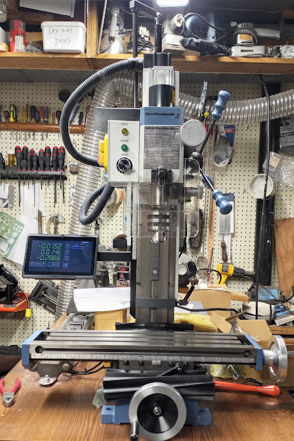
I chose the cheapest milling machine from Little Machine Shop that had belt drive, and then went up one level to get the version with DRO (digital read outs). That is as of winter 2021 the HiTorque 4190 milling machine. 

It also has variable speed with no gear shifting. The belt drive is quiet and robust. They have smaller machines with plastic Sieg gears that break and are extremely loud. 

This LMS machine has more horsepower, DRO, more work area than the other machine I was looking at: a Taig. The Taig is a very nice machine--and a great deal at half the price! However, I wanted to make large items in addition to watch parts. This meant the Taig was a bit underpowered.

The Taig machine is basically their Microlathe II (which I already own) turned vertical. 

It was a very hard decision but the deal-breaker was this: the Taig machine's Z-axis is controlled by a circular hand-crank mounted on the top of the machine meaning to lower the Taig you have to reach up and crank parallel to the ceiling!!! The LMS machine has a regular pull-down crank like a drill press.

If I bought the Taig I would probably have had to buy a slow, metal drilling drill press to drill holes. With the LMS machine I can use it like a super slow metal drill press, or use it as a milling machine. I have other drill presses, but not a big slow one. In the end I would have probably wanted to do something larger and needed a second mill. 

The LMS machine also has DRO. I like digital readouts for things like, let's say: I have a 1mm wide piece of stock in the vise and I want to make it 0.3mm wide. You can't really dab blue DyeChem and scratch a line at the 0.3mm mark on a 1mm piece very easily. I'd probably need to get another binocular microscope--and the work envelope area of the Taig wouldn't allow that anyway. With the DRO I find the edge, hit zero and then mill to -0.7mm, which leaves .03mm left. Easy!

The LMS machine takes R8 size tooling/collets/etc. You can put much larger tools (end mills) into the LMS than you can in the Taig, which takes ER16 collets. To be fair the Taig is a MICRO (not mini) mill. 

Also, since the Taig mill is literally the Microlathe II turned vertical I already have the capability in my lathe. I have a Taig milling attachment (which is super nice, and inexpensive) for my lathe. That let's me mount and mill things sideways on my Taig lathe. The view is much better that way for tiny parts.

So, I didn't want to duplicate much of what I had. I can lathe and mill on my Taig Microlathe II and use the LMS 4190 for milling and heavier (slow) drilling projects.


Ordering


My order list from Little Machine Shop for the Milling Machine and all the tooling was: 


1757 Space Block Set (for the Sine Bar).

3068 Surface Plate, Granite, 12" x 9" x 3" (heavy, cheap, flat). 

3535 Sine Bar, 2.5", Fisher  (lets you mount stuff in vise at precise angles--if you use trigonometry, made in USA). 

4084 Tooling Plate, 6 x 12" (lets you mount tiny things on mill table, comes with clamps, made in USA).

4190 HiTorque Mini Mill, Deluxe (with Digital Read Outs / DRO).  

4304 Shim Stock Assortment, 0.0005" - 0.005" Plastic  (for tramming/leveling).

4653 Indicator Arm, Universal, 6"   (for tramming/leveling).

4858 Tooling Package, R8 Mini Mill Premium (the best package) .

5868 Combination Square Set, 12" 4R Precision (lets you easily find center of circle/rod end).

5874 Machinist Square Set, 2" 4" and 6" (three L-shaped things).

6258 Clamping Kit, 8 mm, Professional Grade 8-Piece (even more extra clamps for the tooling plate, which I probably didn't need).


6294 Tap Guide, Reversible (I think this was actually for my lathe).

2675 Clamps, Screwless Vise (this was for a little screwless vise I already owned).


Doesn't look like much, but that's 305lbs of stuff. I would have almost doubled the tooling, but I already have a bunch from the lathe. I also got stuff from Amazon and eBay. 

Budget for that: the cost of the tooling equals that of the machine. 

I bought the 4653 universal arm and the 4303 shim stock assortment. They have a package of these two things along with a dial test indicator gauge in a nice cheap set; however-I just got a SUPER nice Mitutoyo dial test indicator, so I'm sticking with that and just bought the other two components separately. This is for tramming (leveling) the milling machine. You measure, loosen the column and place thin shim stock under the column's base and re-tighten. I'm hoping it just arrives perfectly level out to .0001" and I can ignore it. One can hope for lots of things though.

I could have saved some cash by delaying the purchase of the Sine bar and the spacer kit for it. However, that's a lot of weight and LMS ships tooling purchased at the same time as a machine for FREE so I just got everything.

I got the most expensive tooling package for the 4190 Mill. It came with the most stuff. It also came with the best stuff. Machining stuff comes at tolerances/accuracy of: .001" or .0005" or .0001". If figured that if I started off with cheap stuff that is less accurate I'd never do what I want. If your vise and measuring tools and spacers and blocks are all cheap and off more than the best stuff that error adds up...and I need all the help I can get. 

Buy once, cry once for the good stuff. I'd rather buy once and be happy, than at some point have to figure out why I can't get something build correctly--and then realize it's an inferior gauge or vise that's tilted or some other thing. That's why I bought Starrett and Mitutoyo magnetic bases and gauges and surface/height tools.

Shipping


Here is the shipping list with box(?) codes. It shipped a few days after Thanksgiving and they didn't send any tracking email yet.

4190 HiTorque Mini Mill, Deluxe Trk

1757 Space Block Set RRB A1  
6258 Clamping Kit, 8 mm, Professional Grade 8-Piece RRB A1
4653 Indicator Arm, Universal, 6" RRB A1  

5868 Combination Square Set, 12" 4R Precision RRB A2

4084 Tooling Plate, 6 x 12" RRB B2 

2675 Clamps, Screwless Vise Sml FRB  
3535 Sine Bar, 2.5", Fisher Sml FRB  
5874 Machinist Square Set, 2" 4" and 6" Sml FRB

4858 Tooling Package, R8 Mini Mill Premium Std Ctn
3068 Surface Plate, Granite, 12" x 9" x 3" Std Ctn  
 
6294 Tap Guide, Reversible FR Ep
4304 Shim Stock Assortment, 0.0005" - 0.005" Plastic FR Ep  


Possible shipping codes, these are my guesses:

Trk = Tracking? The big crate that is tracked?
RRB = regional rate box?
Sml FRB = small flat rate box?
FR Ep = flat rate envelope? Padded?
Std Ctn = standard container? 


It arrrived from Pasadena to Metro Detroit on the 8th day after it was picked up by the shipping company. The shipping company had tracing (which is just another name for tracking). One morning I got a call from the truck driver saying they'd be there in about 35 minutes. They were!

On paper the mill doesn't sound that heavy, but strapped to a heavy dolly/hand-truck it was a bit scary to take down the stairs to it's new basement home. One person holding it a top and two people down the stairs blocking so it only rolls down one step at a time. 

Lifting it from the dolly to the desk bench it seemed a lot lighter. The dolly turned out to be quite heavy just by itself.

Turns out there were heavy items in with the mill and also the DRO tablet was taped to the bed! Probably should have taken that out before going down the stairs--if nothing else, just to save weight.

We had the crate tipped back and loosened all four bolts that held the mill to the crate floor. I believe they were Allen head bolts that took a 6mm Allen key wrench. We put the entire crate on the table and then took off the front of the crate. Totally removed the four Allen head bolts and just pivoted the mill off the box and onto the tabletop. It was very cold and greasy, so I went back to work to let everything warm up from the wintery truck ride. 


Setup

Day two was wiping shipping grease off the machine (don't start the machine up without doing that!). 

They included a little bracket and 3 screws in tapped holes to hold the DRO tablet. Unfortunately it doesn't fit without a little grinding. The forward facing corner (right side/top) needed to be ground off. 


It's not mentioned in the manual, but I matched the 3 little screw holes with 3 little screws that were already loosely screwed into the left side of the column. THANK YOU Little Machine Shop for pre-drilling and tapping those holes! The plastic hose conduit can knock the tablet off the stand if you lower the head-velcro or a rubber band is needed for safety.


They included the owner's manual for the lesser model, but it's an old manual. It doesn't show what this little lever/knob combo does. Facing backwards the machine turns on. Facing up/down/forwards the machine will turn on but you have to hold the power button down. Also, it makes a horrible clanking noise! 


I think this is a magnetic interlock thing? There is a depression in the spindle that I think clacks against a stop mechanism...but not enough to actually stop the machine from spinning. It's like a safety that doesn't work! Or it's something else? It's not in the manual. I'm not sure how a lock that still lets power to the machine (if you press and hold "ON") is a safety feature. Either the machine is off or on. Having one-and-a-half on/off buttons isn't any safer--especially since the .5 doesn't really do much? I dunno. Would have been nice to put that in the manual.


Here is the machine.


Here it is in the dark, showing off the tablet DRO and green light showing it's on.


Anyway, the four bolts that came with the machine are very nice. However, they are too short to go through the big 2" slab of tabletop I'm mounting this machine on.

I used a Wixey digital level and a couple spirit levels and got the bench top leveled. Then I leveled the machine with the levels on the XY table. Left to right the XY table is at 0 degrees level: perfect! Front to back (if the machine was falling toward or away from the user) the machine is 0.1 degree level: almost perfect. To be clear this is the entire table top and entire machine--this is NOT the tramming of the mill's column. That's way more precise.

I have drilled the 4 mounting holes to attach the mill to the benchtop. Just waiting to get four longer bolt's: 3" long threads instead of the 1 3/4" shipping ones. I'll reuse the nice washers that came with the shipping bolts.

Shimming

I shimmed the left two bolts on the column to bring the left/right table level.

Then I added shims to both the front column bolts to lean yhe the column back (to reduce the "nod" of the head).


I used the Little Machine Shop shim set. Thicknesses weren't labeled on the package.

I got the right to left table to .001" and the front to back .002" which the manual says is good. It takes a lot of bting and unbolting the column screws. Easy but hard, like walking 50 miles: step by little step.

The vise. Enraging: to mount the big swivel vise you throw away the huge bolts that come with it and use the (pay extra) vise mounting bolt kit.

They tell you that you can't use the swivel mount. Hmmm... Then why did i pay so much extra for to he swivel base vise?!

All you have to do is ditch the tiny washers and cut and grind the threaded rods in the vide mount kit down.

You will end up with less than a .001" clearance between the top of the nut and the bottom of the vise, but it will swivel just fine.

Cut with a hacksaw, then grind a little.


You  can't even see light between them but the vise is mounted and it can still swivel!


...and here is the culmination of 3 years of research, planning, procurement and setup: a mirror smooth milled channel. Done with a 2 flute roughing end mill (too slow pm and no coolant, lol).


Beautiful irridescent and smooth.


Wednesday, November 10, 2021

Watchmaking Machinery 2 DRO Cross slide


I ordered a digital caliper DRO (digital read out) for the cross slide of the Taig lathe off of eBay.

Well: it was stuck on its bracket with tape; the tape pulled the back caliper sticker off and the anchor point tape came off too; the bracket was some purple transparent 3D print stuff that was less rigid tha PLA; also the anchor bracket had a twist which caused the slide to bind.

The calipers had the measuring jaws cut off. That was the only good thing-other than the whole thing was a sort of inspiration template for me.


So I cut an aluminum block into a "C" shape with a drill press, hacksaw and jeweler's saw to connect the drilled holes.


Then i remembered I got my bandsaw running straight (by twisting the table and adding more tension). So I popped a bi-metal blade with tiny teeth on it to help with the rest.

I made the anchor point with a drill hole that was also counter sunk most of the way down. I didn't go all the way down so the part of the hole that narrows down would grab the head of the screw and keep it from pulling through when i tightened the t-nut (which is just a screw and tiny nut).

The Allen key wrench is on the screw in the photo. Then I bandsawed the top quarter of the tiny anchor off. I then drilled two screw holes in a bracket and the anchor pieces, paying careful attention not to go down the center so I wouldn't interfere with the Allen key wrench path.

When tightened, the two halves trap the end of the calipers. As the cross slide moves toward or away from the operator it pushes or pulls the caliper slide which measures the movement to .01 of a millimeter. You can also hit a button and it displays inches.

Anchor point is solid. The plate over the caliper slide end is raised, because it's acting as a clamp. Standing normally it isn't apparent to the operator, and looks pretty cool.

The big C-block is super sturdy. A screw feeds up from the bottom to a nut that is in that T channel.


A single screw holds it to the block. This allows it to pivot counterclockwise for installation and removal. It also allows me to make sure the slide is perfectly parallel to the carriage and slidebefore tightening the anchor point at the other end.

The C-block is most of a 1" x 2" x 4" bl9ck of aluminum. Much, much stiffer than the 1/4" thick 3D printed plastic bracket which visibly flexed.

My C-block doesn't move. Sliding out and returning to starting point gives me a repeatable readout of "0.00mm". You don't get much better than zero-hundredths of a millimeter.

Watchmaking deals with 0.3-0.8mm (tenths), which is much larger than 0.01mm (hundredths).

Meow²