Saturday, October 2, 2021

Halloween 2021 Pumpkin Contest


Halloween 2021 Pumpkin Contest @ work


Old defibrillator, IV bag + stand, and a red pumpkin. 

I can't decide whether to call it "Mama told me to make some friends, so I am" or just "I heart Halloween".

I put veins on the red pumpkin with some hot glue gun glue. That worked out well. I had a jammed glue gun and was spraying the glue onto a paper towel to unclog it--then I realized it'll be better to put that on the pumpkin. 


Sunday, September 19, 2021

Supra Advantage Express II real estate lock opened

 Supra Advantage Express II 

Real Estate Lock Opened 


These locks have: a big shackle to attach the lock, and a small drawer that opens and gives the real estate agent a key to the house so they can show it to potential buyers.   

These locks are digital, and though they have a removable keypad you need to update a PAID subscription service to get the keypad to actually interact with the lock. There are cool reporting functions (what agent got the key out, when they did, when they put it back, etc.). 

I have the manual, the keypad, a new odd battery for the keypad and the actual lock. No good. This is a bypass...with a hammer. 

 The lock still functioned (locked) afterward and I can do this over and over and still lock the shackle. It take a good wack or three on the side of the lock, near the top to open the shackle because it is spring retained. 

I was using a lead hammer, but one of the transparent yellow plastic headed hammers would probably work better since you're trying to basically vibrate the metal components against the spring tension to pop it open. 


Below is the mechanism for the house-key compartment at the bottom of the Supra Advantage lock. 


It is basically two metal pins (on at each end) and a winding of red lacquer-coated magnet wire. Power (probably 12 to 24 volts DC) goes through the wire and it pulls in both pins. That releases the little drawer in the bottom of the lock so you can get the house key out. 


Here is video of just about 9vDC making the pins go in and out. Higher voltage would make them go inward farther/longer time allowing the drawer to spring open.


This little drawer can be defeated by hitting the lock, near the bottom (but on the side) with a plastic headed hammer. 


One of those with the transparent yellow heads. This can for the pins (and the springs that hold them outward/locked) to jiggle around and the drawer will fall open. Or it will jam. 

There are 3 hollow split pins at the bottom edge of the lock. All those do is keep you from slamming the drawer too far shut. They have zero value when physically trying to break the lock open.

Sunday, September 5, 2021

Micro Precision Drill Press Watchmaker Drill Press


So, making wristwatch parts requires teeny-tiny little drill bits (0.3mm). For fun I took my mini cylindrical drill, a drill press stand and a magnifying LED light with clamp and made my own micro precision drill press.


I shopped around: a USED micro drill press is close to $8000. A crappy one is $350. This cast iron beast was way, way, way less than all that.


Feast your beady little eyes on my sub-millimeter hole shooter (explanations after the photos):


This stand is fantastic. I added a "micro drill" to it instead of a corded drill. This is for micro drilling. I'm using drill bits with diameters of LESS than a millimeter usually. Watchmaking 0.3mm to 2.4mm bits usually. Some of them are literally thinner than a human hair. Most people buy these for CORDED drills with clamping collars (i.e., most corded Milwaukee, Metabo and Wen drills).  


This stand is VERY heavy for its size due to its cast iron base (I checked it with a magnet). The magnet stuck to all the green parts. The magnet did NOT stick to the yellow part (the moving dovetail part of the head and the drill collar clamp part). The magnet also stuck to the actual column, meaning it's steel and not aluminum. The rotating part of the head is green and steel. I'm not using that function, but it's still nice. 


The jibs (part that the dovetails rub against) are replaceable copper strips. The dovetail tightness can be adjusted by screws. Yes, you can fine tune this thing just like a lathe or milling machine. That simple thing is a HEAVY DUTY feature in any machine.


The spring is fairly hard to pull down without a drill in it. I'm assuming once you put a heavy corded drill in there it will pull down easily. My cylindrical drill is very light comparatively--so there is a little extra pressure needed. Although it's not bad. If it was a problem you just unhook the bottom of the spring, and pull it up out the top and replace it with a weaker (or stronger) spring to suit your taste. I'm just happy that the flat pinion rack (flat part of metal that engages with the gear when you pull the lever down) is nice and smooth. VERY smooth.


Here's a tip: if you don't want to bolt this to a bench top you can bolt three rectangular blocks of wood to the underside of the base. The left/right support the press on a table/shelf for storage. Then when you want to use this thing you clamp the center block of wood into a vise. I have that on some mini-vises that can clamp into bigger vises like Ukrainian nesting dolls. LOL! Anyway, YOU NEED TO CLAMP/BOLT/SCREW this to a work surface--it's not super tippy, but when you pull down on the lever it will be. The base has holes in tabs in all four corners (plus one huge hole in center). 


When open the circular hole that you clamp on your drill collar is 43mm. My cylindrical drill has a diameter of 40mm. I needed one of the (three or four) plastic sleeves they give you to assist clamping smaller collars. That 3mm thick sleeve really made a difference. 


In my photos I show a 1mm drill bit in my drill--but shown through the magnifying lamp I added. My intention is to add a wooden base with a couple drawers for tiny drill bits--and then mount the speed control for my drill (0-13,000 RPM) to the LEFT side of the cabinet. That way I can adjust the drill speed with my left hand while pulling down with my right.


Things I would change:

It comes with FOUR Allen key/wrenches because they used FOUR different sized Allen bolts. One of the keys only fits the bolt for the arrow pointer head thingy on the depth gauge. It doesn't matter to me, but they'd have to buy/store/track 1 less bolt size, 1 less nut size, and give away 1 less Allen key if they just settled on THREE sizes of bolts. They could probably just use TWO sizes. 


The depth gauge has "6" at the top and "0" at the bottom. That means as you pull down on the drill your depth gauge is reading backwards. A two centimeter deep drilling hole goes from 6 to 4--instead of 0 to 2. I've seen that on other tools, and it's annoying.


The cap on the top of the column has a little hook for the drill power cord. It's very open and the cord can fall out. No big deal, it's probably loose so the cord doesn't catch and the drill moves down--but maybe a "V" shape that contains the cord and let's it move rather than a "C" shape that lets it fall out. With that said, my drill cord and my magnifying light cord seem pretty happy--and I can always zip-tie them loosely if need be. 


Why did I do this when I have other BIG drill presses, lathe, etc.? I'm playing around with a couple of wristwatch movements and wanted to drill REALLY small holes. I started looking at tiny drill presses: garbage plasticy ones for $80; garbage plastically ones for $350; nice ones at about $1000. Really nice ones up to $15,000. Yes, the price of a car--for a teeny tiny drill press. Look up used "Precision drill press" and you'll be amazed. No thanks.


There is a somewhat similar drilling stand which looks cooler (all steel) but it looks like it has rack and pinion metal-strips pop riveted together as it's movement mechanism. Lots of sideways jiggle and non-repeatable drilling (can't hit the same hole twice). No thanks.


To be clear: the magnifying light and cylinder micro drill DO NOT COME WITH THIS THING.


Anyway, I would go this route versus a sub-$1000 precision drill press. Anything under $1000 is going to be trash. Make your own setup with this.


M1K3 FR0M D3TR01T

Tuesday, July 6, 2021

DIY Easy Double Slit Experiment

DIY Easy Double Slit Experiment


Items needed:

2 paper binder clips (any size)
1 large paper binder clip
2 razor blades
1 sewing needle
1 laser pointer
Wood or cardboard base to stick pin into


Put binder clips on the razor blades so they stand up.

Jam the pin so it sticks upright out if the wood or cardboard base (I used a wooden cigar box).

Put the laser pointer into the large binder clip.

Keep moving the razor blades closer and closer to both sides of the needle. 

The dual nature of photon particles vs wave theory; classical vs quantum physics!

Eventually you'll get interference lines.

Sunday, June 13, 2021

AIPHONE C-ML Intercom Door Lock

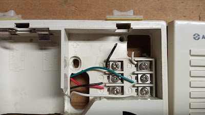
 AIPHONE C-ML Intercom and magnetic door unlock wiring system.


Outside the building a delivery person presses the doorbell button on the LE-D unit and lets go. This rings a loud bell on the C-ML.

Inside a security person presses and holds the microphone flip switch on the C-ML and talks into it "how may I help you?" and then lets go of the switch-which in turn activates a microphone on the outdoor LE-D unit.

The outside delivery person has a few seconds to speak "your sandwiches are here!"

The indoor security person can then press the little black door unlock button which cuts power to the magnet holding the door open for a few seconds allowing sandwich to be delivered.

Alternately, a person can swipe a magnetic swipe card in the REI reader, or type in a code on the REI keypad and the door magnet will unlock for a few seconds.

With short runs of wire during testing only 3vDC was needed for the intercom and doorbell to work. I also have a 16.5vAC Revere wall wart that might work on parts of this system-possibly feeding the keyboard logic boards and magnet lock "brain" (still playing around).


Green wire on left, white on right.


When the little black door unlock button is pressed on the C-ML the ohm resistance on the green and white wires change. There is no voltage, this acts as an on/off switch for the door magnet/keypad part. 

There are a lot of wires on the keypad that interface with the unlock button, card reader and the magnet lock. I'll update in a week or two when i open that up and wire it in. 


Left top/Black wire/Door open (ohm continuity)

Right top/White wire/Door open (ohm continuity)

Middle left/Black negative DC power
Middle right/Green to LE-D doorbell


Bottom left/Red positive DC power
Bottom right/White  to LE-D doorbell


Now i have to wire up the keypad "brain" of the system and the keycard slide reader.


"Just slide the sandwiches under the truck...meow."

Thursday, May 27, 2021

Unlock DVD security case with red padlock


Place rare earth neodymium magnets (the super strong chrome looking ones) as shown. Then slide them together at same time.

These were tiny 6mm magnet cylinders from K&J magnets store. I had to double up and use two per side to make it easier.

Slightly larger magnets would have worked even easier. I have some 1" cube N52 that make it even easier, but i wanted to see how small I could go. A single 6mm cylinder on each side might barely work if you practice...but just stack a couple and you're good to go. 

Placement matters. The magnets still still stick on the DVD case of you switch sides, but they won't unlock it.

Bottom of red padlock side = top left.
Top of red padlock = bottom right.

Worst part is pinching your fingers with N52 magnets: very painful 😖


...and here are a couple, slightly larger magnets I sunk into a hunk of scrap wood. Works great:


Monday, March 29, 2021

Updating the BIOS on an ancient Acer Aspire One KAV10 AOD150-1322 laptop running Linux Mint 19.3


Updating the BIOS on an ancient Acer Aspire One KAV10 AOD150-1322 laptop running Linux Mint 19.3 to get rid of a problem when it was booting up and shutting down it would go to sleep multiple times during these processes. I had to keep hitting the space bar and sometimes the power button to wake up the laptop so it could continue shutting down or booting up.


The problem would go away if I went into F2 on boot up and turned off the fast start/quick start/ready start quick boot up feature. But then it would loose this change after one or two boots. So I decided to flash the BIOS to the latest version available (a version from way back in 2012!).

The only reason I did this (it took about 3 hours to get past all the wrong advice online) was because the laptop kept going into sleep/hibernate in the middle booting or shutting down. Only attempt to update BIOS on any machine if there is a need. If it goes wrong BIOS problems tend to be unfixable and you can just throw the computer in the trash!

To do this I needed:

-USB stick.

-The Acer Bios files from the ACER website only (comes with Windows and DOS folder--you have to use the DOS folder files).

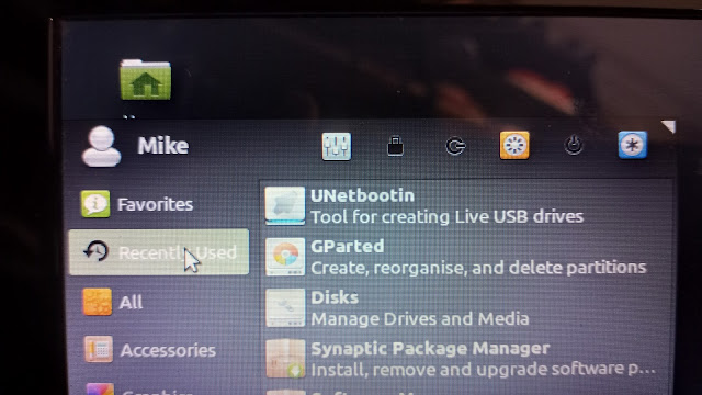
-Unetbootin program loaded.

-GParted program loaded.

-Disks (or Disk Management) program loaded.


Many of the online tutorials are WRONG WRONG WRONG!!!! in their steps. Specifically they tell you: the wrong FAT system, the wrong BIOS file to choose, and a couple other wrong things.


After downloading the BIOS files from Acer and loading the Linux Mint programs on the laptop I was ready to begin.


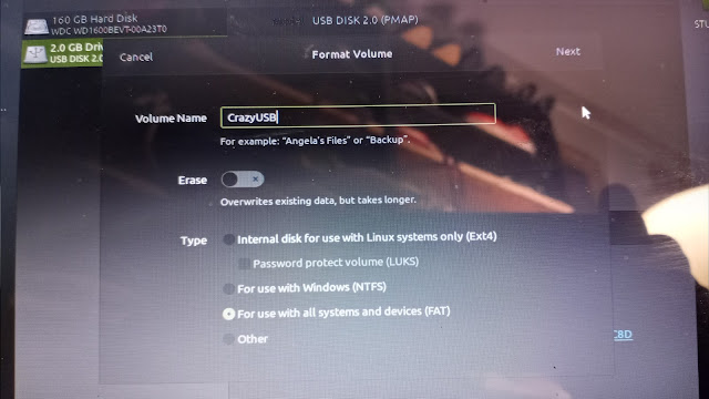
Formatting the USB stick. First off, many tutorials say to use FAT16 but that never worked for me so I used FAT32. When you name your USB make sure to use  8 or less letters in the name. I named mine "CrazyUSB". Keep the name short or else some of these old DOS things will have an issue!


Also when using the programs you MUST make sure you've selected your USB thumb drive and NOT your computer's hard drive. These programs ALL default to your computers hard drive and then you have to select the USB stick (green selection in upper right corner in the photo).


I did this multiple (failed) times and eventually when there was a PARTITION on the USB stick it went better. The USB partition now showed up as "SAFA-CC8D" instead of "CrazyUSB". This is apparently an important change in how the USB stick was formatted. It was still FAT32 but partitioned with Gparted so the above photo may not be the correct way!!! Sorry, but it's all I have.


Look below at this photo. That is what the final, successful USB looked like. But we'll get to that.


After formatting the USB into FAT32 (probably then adding a partition in it) we download the BIOS files from the Acer website. You must go to the Acer website and not some of the other various scam BIOS websites. Acer has it!

The folder might say "Windows" on the outside but when you go inside you want to be working with the DOS files in the DOS folder.


We want the 3 files from the DOS folder (ignore the windows folder).


Start the program Unetbootin and only click the top settings. Select the dot for "Distribution" and select "FreeDOS" and "1.0" and click OK. This downloads and formats FreeDOS to your USB stick.


Here's where things get confusing. Some people say you can just drag and drop your 3 BIOS files (Flashit.EXE, KAV10.BAT and KAV10.FD) but what I did was do start Unetbootin again.

Click to dot the "Diskimage" and select "ISO" and then browse to find the DOS file called FLASHIT.EXE and click ok.

Then I grabbed the other two files (KAV10.BAT and KAV10.FD) and just dragged and dropped them into the USB folder.

To be clear: we are using UNetbootin to LOAD the Flashit.EXE file and closing UNetbootin. Then we are just dragging and dropping the other two files with our mouse.


Finally getting to the actual BIOS update. After getting the computer to boot from the USB properly you'll see a countdown. I had it hang up and keep counting down from 10 seconds and then starting over and over again. It's a blue and grey screen that says "default" on it. Eventually after repeatedly trying slight variations on the above steps I got it to actually bring me to a boot screen where I had choices:

1 was the default (someone said never use that for some reason) so I chose either 2 or 5. I think it was the "5" boot as live disc, etc. 

I finally got to a Insyde bios screen with an "A prompt". You have to change the A prompt to a "C" prompt, and then choose the BAT file (NOT the EXE file) to run.

I was at the A:\> and 

Type C:
Hit enter
You should now have a C:\> prompt
Type KAV10.BAT

Then came this glorious screen:


You can sit and watch the FFFFxxxx blocks updating. It only takes a minute or two. Then your computer will reboot itself.


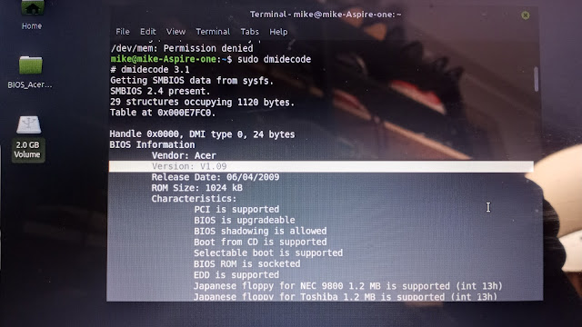
Go into Terminal and type "sudo dmidecode" to view your important stats, including the BIOS which you'll have to scroll up to the top of the list to see.


Success: now it's V1.09 which is the last update to this BIOS as of the year 2021. It will probably be the last BIOS update for the old Acer laptops from the 2000s.


So here are the errors in many online tutorials that I had to get past:

-Fat 32 (not Fat 16).
-Partition Fat 32?
-Use the DOS BIOS folder items (not the Windows BIOS folder items).
-UNetbootin loads DOS 1.0 itself (you don't have to download other DOS things).
-Load the EXE file (don't just click and drag it), but then click and drag the other two files!
-Once at the C prompt type in the name of the BAT file (not the EXE file).

It is pretty impossible to take screenshots while doing DOS/BIOS/Linux stuff like this so it's just cellphone photos that I wasn't intending on using online--just notes in case everything went wrong--which it did for 3 hours. I just pieced back about 98% of I what finally worked. Still hazy on how the USB was formatted to FAT32 (and then partitioned I'm pretty sure also in FAT32 using GParted?).

The only reason I did this (it took about 3 hours to get past all the wrong advice online) was because the laptop kept going into sleep/hibernate in the middle booting or shutting down. Only attempt to update BIOS on any machine if there is a need. If it goes wrong BIOS problems tend to be unfixable and you can just throw the computer in the trash!