Friday, August 7, 2015

Bench Top Laboratory Power Supply


Bench Top Laboratory Power Supply


I was going to buy a bench top power supply, but I wanted to build one on my own to learn about them first. So I soldered together an Elenco XP-720 AC/DC full-wave rectified 15v negative or positive DC 12.6v AC center-tapped 1 Amp supply with 3 Amp at 5v DC power supply.


That's a heck of a long name, and I wanted to learn what all (at least some) of that meant. I learn by doing. I'm not one of those people who go around saying, "you should..." or "somebody should..." do whatever. I do what I do.

One thing I don't do so often is solder. It's been a while, so I soldered up my last project to practice. I still have the soldering iron my father gave me when I was ten years old. Although more and more solder is the horrible lead-free type. 

And now a brief rant about solder that you can skip:

Lead-free solder is poisonous to the person using it.

Leaded solder is not poisonous.

Lead vaporizes at 1100° F, which is way higher than the temperature it melts at. You will encounter zero lead fumes while soldering. This is a scientific fact you can easily research yourself. Weller is a company that sells fumes extraction safety devices and even they say the lead isn't the issue, it's the flux (more on flux below).

Lead-free melts at a higher temperature (making work less well), spits hot droplets more to burn your arms, and gives off terrible fumes. It also is porous, meaning even if used properly if will fail way sooner than lead solder. It also is more brittle. You will risk your health to build an inferior item for the benefit of...?

The governments of the world want to protect theoretical people who don't exist from drinking well water on garbage dumps from having old electronics in land fills somehow leach lead into the water...but wait, they wanted to ban plastic bags because no water or air gets to them in landfills to decompose them?

They are poisoning solderers to protect people who drink water from garbage dumps.

The safest choice for solder in your home is lead.

The most dangerous part of any solder is the flux in it. It's made from pine tree sap and breathing the fumes (or even having the fumes contact your skin) can cause a long list of dermal and breathing problems because those fumes contain formaldehyde, hydrochloric acid, all sorts of benzines and toulines and phenols that are just bad, bad, bad. Yes, the trees are killing trying to kill us!
Any way, the future of solder is MesoGlue!  MesGlue is as nanotechnology were there is a jagged piece of Indium. When this is mated with a fitting jagged piece of Gallium it liquifies without heat and creates a solder joint. I love Gallium, it's my second favorite metal, next to Bismuth. Gallium feels like lead, but if you hold it in your hand it will melt!!! Just like liquid Mercury. I have some, and it really melts in my hand. Magicians make spoons out of Gallium, then dip then in hit water to make then disappear (disolve).

Your reward for reading that rant: a nicely laid-out soldering station design:


Here is my messy soldering on a circuit board. I solder wires together all the time, but that's easy: weave the wires together and heat. Apply the solder to the wires, not the iron. You have to be quick for diodes and such-heat can damage them and they're really, really tiny!

You'll notice my 40 year old soldering iron tip is grungy. After this I cleaned it the way you're not supposed to: sand down to the copper, plunge it while hot into plumbers flux (which shouldn't be used with electronics) and add high tin content solder. Tip gets a mirror finish in just a few seconds! All over the internet they say not to expose the copper of the tip, however if you talk with people who use soldering irons for a living they say that if they run out of tips they just jam a piece of thick copper wire into their iron and get to work!


Clipping the excess is easy with diagonal cutters (some call them "dikes" for DIagonal CutterS. I got these Italian made Hakko CHP-170 ones off Amazon for $3 with free shipping!  I wish I had these 30 years ago, they're so good I can't tell the difference between closing them empty or actually cutting excess circuit legs/posts/leads off after soldering.


Here are some lovely diodes that only work when the input power is positive (AC current alternates). One diode gives half-wave rectification so there are two per output. 2 x 60 cycles in US household AC equals 120 cycle output. Full-wave rectified.


The big cylinders are capacitors. They're kind of like batteries. They store current and release it smoothly: making crazy alternating current (AC) into pleasantly stable direct current (DC). There are many here for the various choices of output.

Dead center is a little black half cylinder that is an integrated circuit. It's part of the regulation for the 5v 3a output. It's keeps things really stable: if there's a voltsge drop this drives it back up to 5v. On the Amp side of things, if more than 3a is coming in the grey tube at bottom center shunts the excess to another integrated circuit which bounces in a look to the first one. This will overheat and shut down, which is better than overheating and catching on fire (but I got close, more about that later).


Speaking of outputs: here is a view of the binding posts from inside the box. Black is common/ground/true-earth ground/floating ground/negative depending on how you set things up (if you want to start an argument, just ask what these colors "officially" stand for in AC and/or DC applications). Red is positive output. Yellow is more positive outputs of AC, except one choice here is for negative -15v DC, so I have no idea what that qualifies as when operating in that mode.


The wires are for routing all the lovely electrons through this machine (yes machine: it can change AC to DC and/or vary Amps and Volts, and double the cycle rate of regular household electricity). The big white thing is just the transformer, which we've discussed in previous posts.

Although this transformer is center-tapped: instead of two wires coming out of it, it has seven! This allows you to connect one part of the coil and get half AC output, or connect in to the black post and get full 12.6v at 1a AC output (which might be why it's binding posts are yellow, like the negative DC). Simple, yet fancy.


17.8 Volts at 1 amp. Enough to kill. 
It's the Amps that kill. 1 is enough. 

17.8v x 1A = 17.8 Watts.

There is another output that outputs 5 Volts at 3 Amps. Even though that's only 15 Watts, the 3 Amps is enough to kill you three fingers over!


Here I have the positive (+) DC knob turned all the way up, giving me 17.8v at 1a DC.


On the left is my nicer multimeter that I bought to protect my 40 year old one that I love. The one on the right was only $3 and works great. I bought a few to use in situations where the multimeter might be damaged.


The expensive one has a thermometer! That drink isn't cold enough...


...but the $3 one has a built in transistor testing jack!


Most importantly, the expensive one can measure capacitance.

The expensive one also is auto-ranging, while the cheap one is manual. You have to pick the Volt or Amp range of the circuit your testing. Pick the wrong one and zap! Everything in electronics is crazy decimal places that are all abbreviated with k and m and M so it's easy to confuse ten volts (10v) with ten-thousands volts (10kv) when squinting at a circuit board.


Speaking of damage: below is a 10uF 25v capacitor which I blew up, literally! Pop!

You see, firecrackers are rolls of paper with gunpowder sprinkled inside. Capacitors are rolls of paper with oil sprinkled inside. Can you tell where I'm going with this?


To get full 12.6v power you connect a yellow post to the black. I connected yellow to yellow on the wrong (DC) side and bang! Shreds of paper all over the inside of the box. It was very loud. So I spent $5 and got 100 capacitors off Amazon as backup. It could have been a deadly mistake: wrong color and wrong side. This is why I don't go mushroom picking.

Now I have a ton of new knowledge about electricity and my very own power supply for further experimentation.


So, what's the first thing I did with my power supply besides testing? Lighting up an old vacuum tube. I put red marker on the two heater pins, which I found by using a multimeter on Ohm/resistance setting. These were the only two that had an actual reading. These two pins were, by the way, totally different than the two different schematics I found online!


I ran two power cables from my power supply. Since this is a Tung-Sol vacuum tube with a part number "6K6GT" I knew the heater takes 6 volts. The first number 6 is the one that tells you the voltage. Other tubes use 12v and thus have a 12 as their first number. I first tried 6v of DC power, but it only glowed with a barely visible pin point. I raised the voltage to 8v and it glowed more, but I was afraid of blowing the tube.


It wasn't super bright, like some tubes, but I did glow better when I hooked it up to my power supply's fixed 6.3v AC outputs. AC worked much better than DC.


Power supply update: I did buy a fancy looking store bought supply... the results were not good:


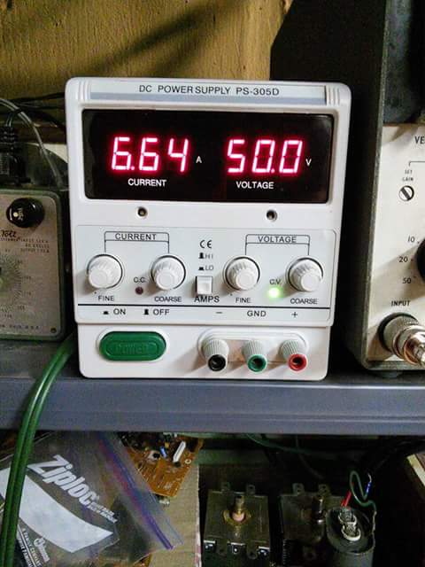
Oh dearest brand new Fling Dung Industries PS-305d 30 volt 5 Amp power supply, you died as you lived: somehow blasting out 50.2 volts at 6.66 Amps uncontrollably for about sixty seconds before your capacitor exploded.

Hopefully I'll get a return authorization and lug you to the post office. Seriously, this is I think the first thing I've ever returned to Amazon in twenty years of shopping there. [Update: return shipping from UPS and USPS was more than the refund would be. Do not buy this power source, which is sold under dozens of names. After re-recontacting the seller they sent a free shipping label, I sent it, someone there signed for it and...still no refund].


What! That loud noise wasn't microwave popcorn? Do popped capacitors have delicious salt and butter to lick off? No?!? Meow!

See Atomic Particles With Your Own Eyes Part 4: Inferrence via Ion Induced Voltage Fluctuations (Welcome to the Ion Chamber)


So You Wanna See Atomic Particles With Your Own Eyes Part 4: Inferrence via Ion Induced Voltage Fluctuations (Welcome to the Ion Chamber)


There is more to seeing than what meets the eyeball.
-N.R. Hanson, Patterns of Discovery


We've explored actually seeing the paths of particles in a nuclear cloud chamber; watched corruscating alpha particles slam against a phosphor screen in spinthariscope; watched them explode when crossing the high voltage spark detector; found fields of activity with the radio telescope; and just horsed around with regular old Geiger Counters for fun. 

It's time to mix low voltage (8.5v) with soldering, multimeters and aluminum foil to make an Ion Chamber.

Simply put: we charge a cookie tin and have a wire inside that acts as a cathode. As ionized particles enter the chamber they create a current flow that is displayed on a multimeter. The higher the volts, the more ions which means greater radiation. 


Cookie tin. 


Screws that join the circuit board physically and electricity to the tin.


The cover of the tin becomes a circuit board cover.


I soldered a wire to the middle post of a Darlington transistor.  This is the cathode that passes through the bottom of the circuit board and into the tin. The Darlington transistor is actually two transistors in one package. The first part amplifies the incoming current, the second amplifies it even more!

A guy named Sid Darlington actually patented the idea of putting "two or three" components into a single unit back in the early 1950s. Not sure how momentous this was. Um, "let's moosh together two pizzas and make a mediocre double-pizza with a soggy crust center." Yeah, no! I think he actually figured out how to do it though, so it wasn't just the dopey idea of smashing them together that was his claim to fame.


Anyway, it acts like a single transistor but it amps up (high gain) the input. However the first of the Darlington ‘pair’ sucks up the voltage and responds in the circuit, leaving the second built in transistor a little ‘hungry’ for more. 

Think of it like two cats in a single cage: first one gets enough food, the second doesn’t so it makes for a really jittery pair of cats. That’s generally bad, but how can we use this to our advantage? 

Darlington Pairs are very jittery = very sensitive! They make create components in touch sensors. What are we doing? Well, we’re building a sensor that detects when it is touched by tiny little ions right? Great! How can we increase the jittery sensitivity of this? By adding that long wire to the middle leg of the Darlington transistor and extending it into your ion chamber. Neato!

Here's a photo of the wire coming off the Darlington straight at the camera.


By the way, I ordered the circuit board and transistor from Madscientisthut.com. They're neat people, ship fast and have cool stuff. You can order an ion chamber kit from them in various ways. In one of the kits they'll even through in a multimeter!! Or you can buy the board and source the parts separately from Radio Shack or wherever. I've found that usually on Amazon you have to buy 100 of the same components-it's cheap, but do I need 100 Darlington Transistors for $5 and free shipping? No, that's where kit designers like Madscientisthut.com come in and make everything easier.

I do order capacitors in bulk, because I get weird and blow lots of capacitors. A just received a bag of 100 capacitors from Amazon, which was a good deal and convenient...as you'll see in my next post about linear laboratory bench power supply making (there will be a loud bang and a little smoke!). 


Ok, here is the circuit board mounted on the cookie tin.


The inside of the cookie tin with the cathode wire in place.


The open end of the tin is covered with aluminum foil. I roughly zeroed out the meter.

Here is that meter during testing with a uranium test source (upper left above the foil).


Back view of the unit with the circuit board guard off and meter reading 15.1 mV. Notice the vial with uranium placed behind the ion chamber.


I moved the uranium to the front (sensing) side of the chamber. Notice the meter has started climbing.


Here's a nifty video I made of it in action. All of this was done before I properly mounted the circuit board deflector guard.


With the circuit board guard professionally mounted (with two different kinds of tape) I can now turn the unit on and use a plastic screw driver to zero in the unit by adjusting a 10k and  a 100k potentiometer through the holes.


Not something I'd have in my carry on luggage, but it works and only took me two nights to build.

The first night I was soldering and half my house went dark. Apparently the 240v electricity from the pole gets split into 120v when it gets to the fuse box. Sometimes with a blown utility pole transformer half the box can go out: either the left side (odd numbered fuses) or right (even numberr fuses) loses power. My basement, garage and half my kitchen worked fine.  All the other rooms had dim lightbulbs that slowly went dark.

"How can a soldering iron cause this?!?"

I finally looked outside and saw the street lamps going dark and realized it was a power line/pole problem. For a few minutes as I sat in complete darkness holding a blazingly hot soldering iron I thought I fried my house wiring.

I got to bed at 3am with a power company using a gas-powered generator backfeeding the pole by my bedroom window. Backfed with a regular old orange extension cord up the pole.  It's very important to wire in emergency generators for your home properly: if you backfeed your house with a male plug to your wall you can kill a utility worker.


Wait, so it wasn't the catnip, er, I mean soldering iron that made the lights in the house look like lava lamps? Still seems dark in here, I can't tell if I'm standing in a pile of loose Darlington transistors or those 10uf decoupling capacitors for the laboratory power source being built for the next post...meow.

Monday, July 27, 2015

Making Waves: Oscilloscopes, Lissajous and a Smattering of Cymatics


Making Waves: Oscilloscopes, Lissajous and a Smattering of Cymatics


Lissajous Figures are curves that are complex enough to make a pattern. These patterns are great tests for oscilloscopes because you can learn information from them by looking at how they move and their shape. They can tell you the frequency, phase, and even angle ratio which you can then look up in a trigonometry sine value for the phase angle of two waves: which lets you figure out the power factor of an electrical component.

Sine waves: sin and cosine. Get it?


Above is a circle I drew with a triangle. The bottom of the triangle is cosine. This is a 45° triangle. Trigonometry and Lissajous Figures are ratios. The ratio of cosine and sine is 70.7% and the angle is 45°. So, sin45 = 0.707. The same priciple applies to waves, but showing it on a circle is easier.

Fancy-smanshy, but we're just looking neat waves here. Lissajous waves are beautiful and quite reminiscent of Art Nouveau "whiplash" style curves and lines used in everything from painting and sculpture to wild furniture and architecture.


So who discovered Lissajous Figures? A man named Nathaniel Bowditch of course! Huh? Yeah, Bowditch experimented with them for a while, then like 50 years later a guy named Jules Lissajous attached a tuning fork to a lightbulb to create these patterns. Previously, people would use a pointed pendulum swinging through fine sand to create what much later became known as Lissajous Figures. I used an analog synthesizer and an old oscilloscope.


I also put a second line out from the synthesizer to a speaker so I could hear the waves while viewing them. A brand new 20Mhz probe and BNC female to UHF male adapter round out this setup.


Lissajous Figures are easy to use. You just count the loops running across the top of the pattern and down the side. This gives you your ratio, a 3 to 1 means 180 cycle voltage, 3 to 5 means a 60 cycle signal, etc. You set the signal input and then calibrate the oscilloscope by at adjusting until you get a familiar pattern. In the above video the settings I talk about are on the synthesizer, not the oscilloscope: I was going for beauty and variation, not calibration.


There are tons of ever more complex Lissajous Figures / Bowditch Curves. Above are the most common ones you'll probably encounter.


Another type of waves are Chladni Figures after Ernst Chladni in 1787 (later renamed Cymatics in 1967 by Hans Jenny). So, who first investigated them in recent times? Our poor, old friend Robert Hooke! You remember him right? He was the guy who discovered "Newton" Rings and "Newtonian" telescopes. I guess we should count ourselves lucky these aren't called Newton Figures.

Cymatics is sound waves directed through water.  Chladni used sand on the bodies of acoustic guitars, but the principle is the similar; although the sand forms geometric patterns that are more hard edged. Here are a few variations of Cymatics waves:


At 456 MHz the water spattered out of the plate:


Shocking and messy!


Here are some still photos of various Cymatic waves:


Chladni Figures are usually made in sand on flat plates. They're basically Cymatic waves in sand but there is a huge difference in how they look because the sand bouncing around, while the sound waves push the water into itself, bumping the waves along: which is why sound travels 4 times faster in water than air! Of course sound moves fastest through our good old friend beryllium from my neutron gun experiment. 


Chladni Figures, related to Cymatics (water and sound waves) showing sounds creating patterns in sand. For more geometric results a square plate and direct vibration coupling works much better. I was piping sound to a metal file cabinet, which then went to the small plate. At first I was bummed they weren't geometric, but after extensive image searching I found exact pattern duplicates from someone using a wooden desk with no plate.

This was just a spur of the moment test after looking at Lissajous Figures on my oscilloscope at 2 AM waiting for the cloud to clear so I can drag my telescope outside.


Here's another attempt:


Again, I found this same pattern duplicated by someone else, so I wasn't totally annoyed at the less-than-awesome pattern. I think once I get a perfectly flat metal plate instead of a slightly domed dish (which was levitating off the surface due to the sound pressure) I think I'll be able to get the hard edged geometric lines. As Paul Camp said, "There is a balance between discovering for oneself and being told."

I'll also be able to better acoustically couple the metal plate to the sound source. I'll update here once it's done, but I'm working on some other projects first.


Just make the noise stop-I can't cover my ears! Meow.